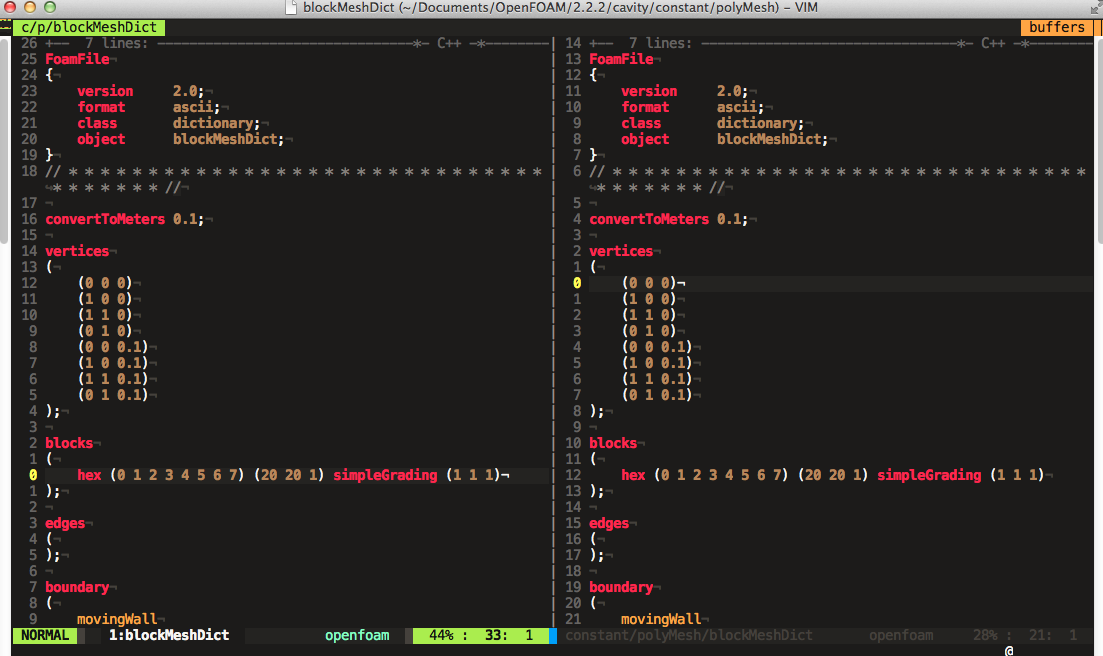
- Entities numbering. To construct a block, an edge or a boundary one has to know its vertices numbers, they are numbered automatically stating with 0. So while constructing a mesh one can, for example, use vim with +relativenumber and blockMeshDict opened in two splits (see screenshot). But when blockMesh reports about errors in the mesh description it also uses these automatic numbers of entities. Soon it becomes rather annoying to look for the block #4 or #17 to correct gradings or densities.
- Mesh grading is a good thing but for example to make a cube mesh with a higher density near the walls, one has to cut the cube into 4 blocks and make consistent grading in each block.
- Curved edges is something special. For a 2D case it's rather simple to make an utility to calculate coordinates of a point on the arc of a given radius passing through two vertices, in a 3D case it's less obvious.
- And finally workflow
vim -> blockMesh -> paraFoamis rather slow.
But it is possible to make hexagonal meshes with it. All GEO files from the sections below can be found in the repository.
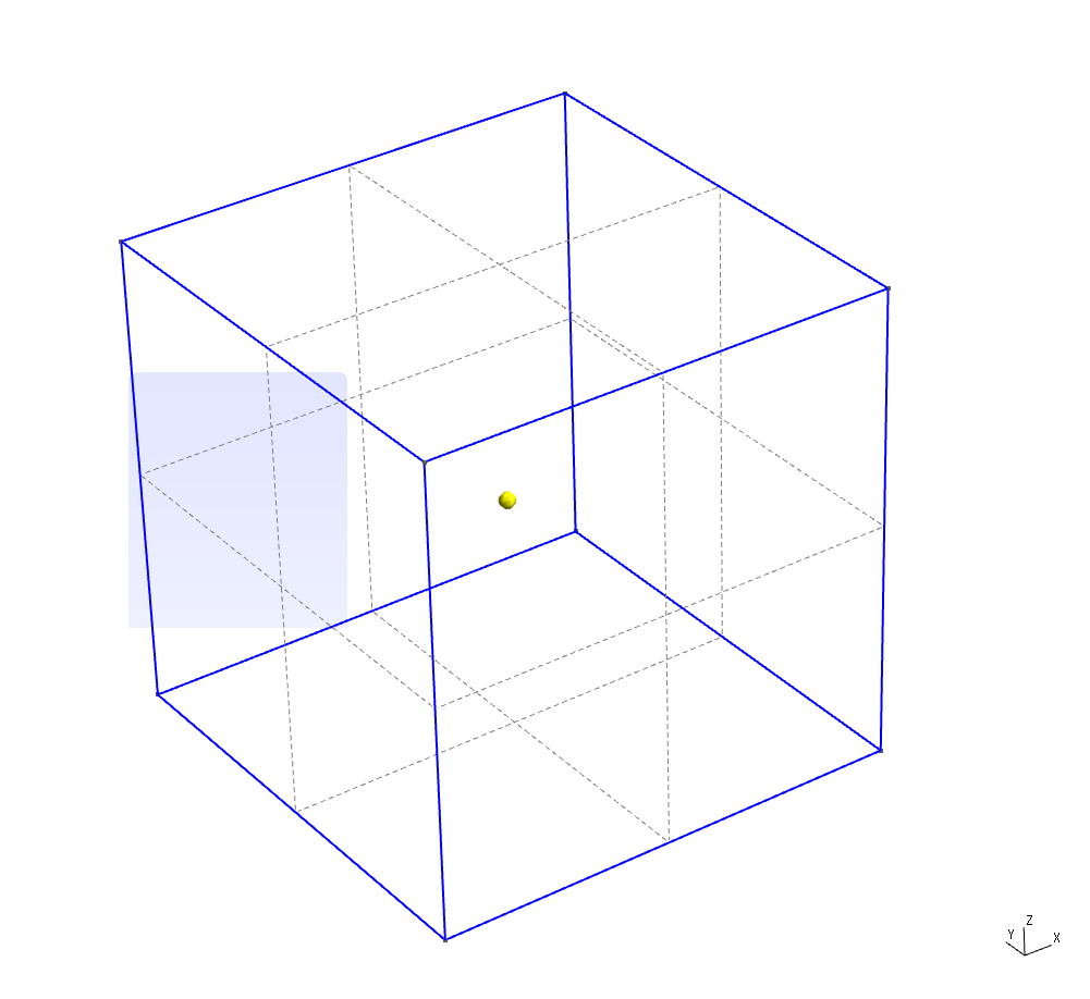
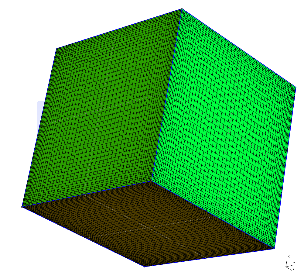
Cube
To make a cube one has to create 8 vertices (with Gmsh's GUI, for example, but in fact it's simpler to create the points in an editor):// Syntax.: Point(n) = {x, y, z, hs};
// As we'll use transfinite algorithm hs can be arbitrary
// or even omitted from mesh description
Point(1) = {0, 0, 0, 1.0};
Point(2) = {1, 0, 0, 1.0};
Point(3) = {0, 1, 0, 1.0};
Point(4) = {1, 1, 0, 1.0};
Point(5) = {1, 1, 1, 1.0};
Point(6) = {1, 0, 1, 1.0};
Point(7) = {0, 1, 1, 1.0};
Point(8) = {0, 0, 1, 1.0};
Line(1) = {3, 7};
Line(2) = {7, 5};
Line(3) = {5, 4};
Line(4) = {4, 3};
Line(5) = {3, 1};
Line(6) = {2, 4};
Line(7) = {2, 6};
Line(8) = {6, 8};
Line(9) = {8, 1};
Line(10) = {1, 2};
Line(11) = {8, 7};
Line(12) = {6, 5};
Surely after to create real 3D mesh one has to define its boundary plane
Line Loop(13) = {7, 8, 9, 10};
Plane Surface(14) = {13};
Line Loop(15) = {6, 4, 5, 10};
Plane Surface(16) = {15};
Line Loop(17) = {3, 4, 1, 2};
Plane Surface(18) = {17};
Line Loop(19) = {12, -2, -11, -8};
Plane Surface(20) = {19};
Line Loop(21) = {7, 12, 3, -6};
Plane Surface(22) = {21};
Line Loop(23) = {9, -5, 1, -11};
Plane Surface(24) = {23};
Surface Loop(25) = {14, 22, 20, 18, 16, 24};
Volume(26) = {25};
Transfinite Line "*" = 100 Using Bump 0.25;
Transfinite Surface "*";
Recombine Surface "*";
Transfinite Volume "*";
Physical Surface("top") = {20};
Physical Surface("bottom") = {16};
Physical Surface("sides") = {14, 24, 18, 22};
Physical Volume("cube") = {26};
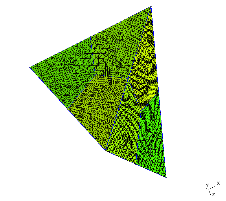
Tetrahedron
This mesh is less trivial than the previous one, the idea of a tetrahedron cut is taken from the article by David Eppstein. Let's assume tetrahedron with the following corners: (-5, 0, -5), (5, 0, -5) and (0, -5, 5), (0, 5, 5). To decompose the tetrahedron into 6-faced volumes one needs to know centers of the sides, centers of the faces and center of the tetrahedron:Point(1) = {-5, 0, -5, 1.0};
Point(2) = {5, 0, -5, 1.0};
Point(3) = {0, -5, 5, 1.0};
Point(4) = {0, 5, 5, 1.0};
Point(5) = {0, 0, 0, 1.0};
Point(6) = {0, 0, -5, 1.0};
Point(7) = {0, 0, 5, 1.0};
Point(8) = {-2.5, -2.5, 0, 1.0};
Point(9) = {-2.5, 2.5, 0, 1.0};
Point(10) = {2.5, -2.5, 0, 1.0};
Point(11) = {-2.5, 2.5, 0, 1.0};
Point(12) = {2.5, 2.5, 0, 1.0};
Point(13) = {0, 1.66666667, -1.66666667, 1.0};
Point(14) = {0, -1.66666667, -1.66666667, 1.0};
Point(15) = {-1.66666667, 0, 1.66666667, 1.0};
Point(16) = {1.66666667, 0, 1.66666667, 1.0};
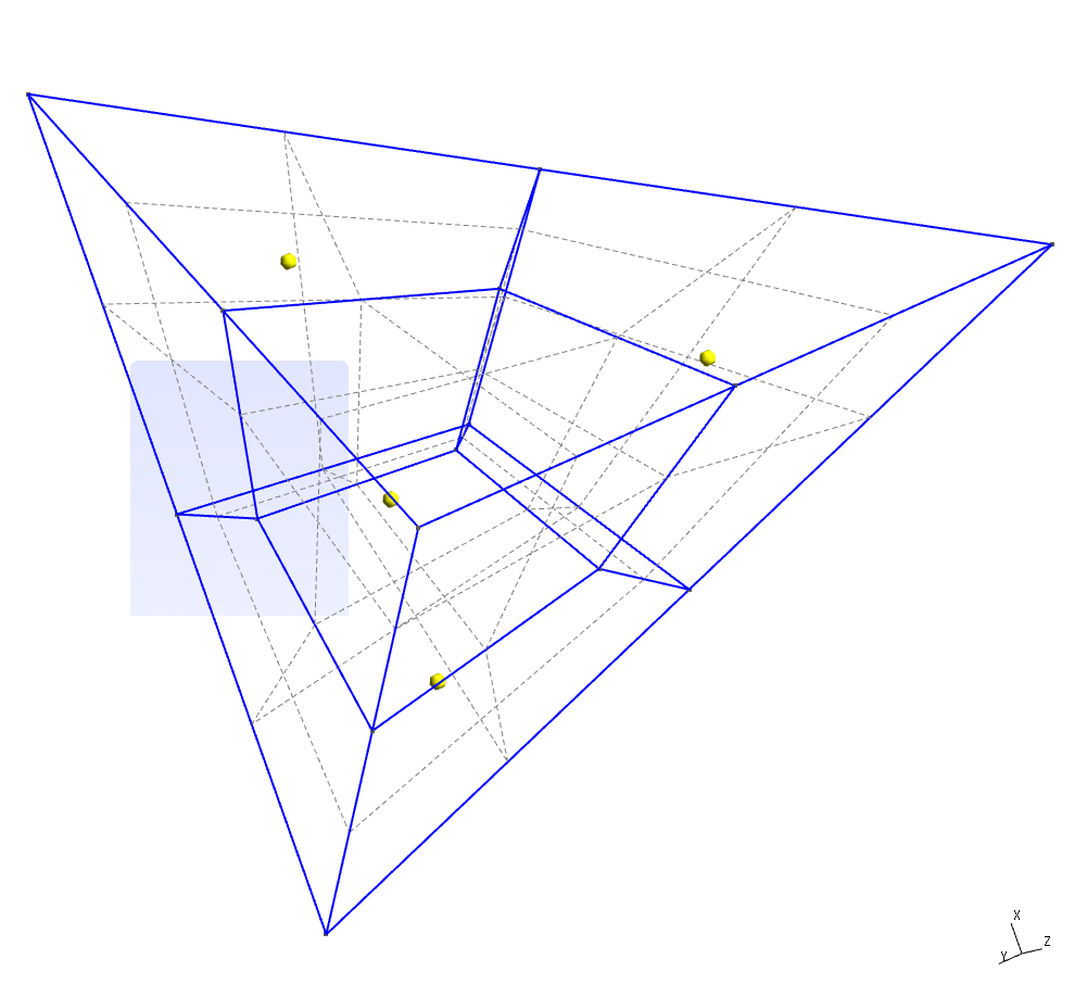
As the densities of the different parts of the mesh should be more or less the same one can add the same four lines as with the cube to have hexagonal mesh
Transfinite Line "*" = 60;
Transfinite Surface "*";
Recombine Surface "*";
Transfinite Volume "*";
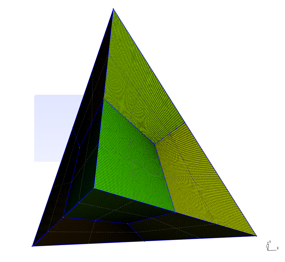
One of the characteristics of the mesh one should check before running a simulation is
non-orthogonality (I omitted this step in case of cube as obviously for that case non-orthogonality is 0). Here is the report of the checkMesh utility for the generated mesh:Checking geometry...
Overall domain bounding box (-5 -5 -5) (5 5 5)
Mesh (non-empty, non-wedge) directions (1 1 1)
Mesh (non-empty) directions (1 1 1)
Boundary openness (1.67777e-16 -6.72996e-16 1.01043e-15) OK.
Max cell openness = 2.87305e-16 OK.
Max aspect ratio = 2.93743 OK.
Minimum face area = 0.00139386. Maximum face area = 0.00798479. Face area magnitudes OK.
Min volume = 4.6248e-05. Max volume = 0.000598376. Total volume = 166.667. Cell volumes OK.
Mesh non-orthogonality Max: 44.2633 average: 22.1599
Non-orthogonality check OK.
Face pyramids OK.
Max skewness = 0.590514 OK.
Coupled point location match (average 0) OK.
Mesh OK.
Cylinder
Trivial solution when one just take a cube and turn it into a cylinder by specifying certain sides as the arcs leads to the highly non-orthogonal meshes. Surely there're many ways to build mesh on a cylinder, below are several variants.Version 1
Top view of the cylinder subdivision looks like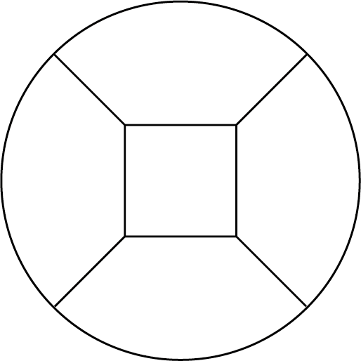
it is a square inside a circle. So we need 9 points (4 for the square, 4 on the circle and one for the center of the arcs) in each horizontal plane.
Point(1) = {0, 0, 0, 1.0};
Point(2) = {3.5355339059327373, 3.5355339059327373, 0, 1.0};
Point(3) = {7.0710678118654746, 7.0710678118654746, 0, 1.0};
Point(4) = {-3.5355339059327373, 3.5355339059327373, 0, 1.0};
Point(5) = {-7.0710678118654746, 7.0710678118654746, 0, 1.0};
Point(6) = {-3.5355339059327373, -3.5355339059327373, 0, 1.0};
Point(7) = {-7.0710678118654746, -7.0710678118654746, 0, 1.0};
Point(8) = {3.5355339059327373, -3.5355339059327373, 0, 1.0};
Point(9) = {7.0710678118654746, -7.0710678118654746, 0, 1.0};
Point(10) = {0, 0, 12.42, 1.0};
Point(11) = {3.5355339059327373, 3.5355339059327373, 12.42, 1.0};
Point(12) = {7.0710678118654746, 7.0710678118654746, 12.42, 1.0};
Point(13) = {-3.5355339059327373, 3.5355339059327373, 12.42, 1.0};
Point(14) = {-7.0710678118654746, 7.0710678118654746, 12.42, 1.0};
Point(15) = {-3.5355339059327373, -3.5355339059327373, 12.42, 1.0};
Point(16) = {-7.0710678118654746, -7.0710678118654746, 12.42, 1.0};
Point(17) = {3.5355339059327373, -3.5355339059327373, 12.42, 1.0};
Point(18) = {7.0710678118654746, -7.0710678118654746, 12.42, 1.0};
3 set of lines can have independent 1D mesh densities, so we define them
// Lines of the square and arcs of the circle
Transfinite Line {1, 2, 3, 4} = 60;
Transfinite Line {17, 18, 19, 20} = 60;
Transfinite Line {9, 10, 11, 12} = 60;
Transfinite Line {21, 22, 23, 24} = 60;

// Lines connecting square and circle
Transfinite Line {5, 6, 7, 8, 13, 14, 15, 16} = 60;

// Vertical lines
Transfinite Line {31, 32, 29, 30, 27, 28, 25, 26} = 61;
Transfinite Surface "*";
Recombine Surface "*";
Transfinite Volume "*";
Below is the output of the checkMesh utility, 42 as a maximum value of non-orthogonality is not catastrophic but I'll try to improve it.
Checking geometry...
    Overall domain bounding box (-9.99911 -9.99911 0) (9.99911 9.99911 12.42)
    Mesh (non-empty, non-wedge) directions (1 1 1)
    Mesh (non-empty) directions (1 1 1)
    Boundary openness (4.94158e-16 -1.11872e-17 -2.57076e-15) OK.
    Max cell openness = 2.46233e-16 OK.
    Max aspect ratio = 4.96072 OK.
    Minimum face area = 0.00750141. Maximum face area = 0.0551113.  Face area magnitudes OK.
    Min volume = 0.00155279. Max volume = 0.00600909.  Total volume = 3901.4.  Cell volumes OK.
    Mesh non-orthogonality Max: 42.4768 average: 7.66228
    Non-orthogonality check OK.
    Face pyramids OK.
    Max skewness = 0.994206 OK.
    Coupled point location match (average 0) OK.

Mesh OK.
Version 2
The first idea that comes to mind in the quest for reducing non-orthogonality of the mesh is to use a square with the curved sides. Let them be arcs with a radius Rsq < Rcyl. Schematic top view of the cylinder division will look like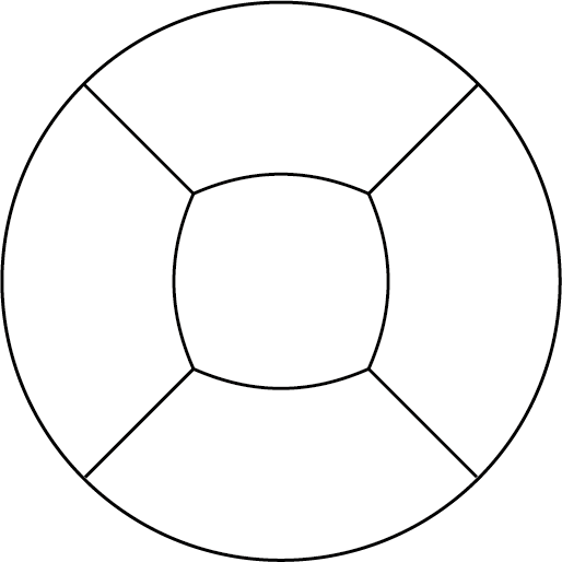
To have curved sides of the square we need to define additional points which will be the centers of the circle arcs
Point(19) = {5.5355339059327373, 0, 0, 1.0};
Point(20) = {-5.5355339059327373, 0, 0, 1.0};
Point(21) = {0, 5.5355339059327373, 0, 1.0};
Point(22) = {0, -5.5355339059327373, 0, 1.0};
Point(23) = {5.5355339059327373, 0, 12.42, 1.0};
Point(24) = {-5.5355339059327373, 0, 12.42, 1.0};
Point(25) = {0, 5.5355339059327373, 12.42, 1.0};
Point(26) = {0, -5.5355339059327373, 12.42, 1.0};
You can see those additional points which are the centers of the circle arcs of the "square" sides. Definition of the entities for transfinite meshing algorithm is almost the same as for the previous case. And here is the mesh
As the selection of the radius for the "square" arcs was more or less arbitrary we got a mesh with higher non-orthogonality:
Checking geometry...
    Overall domain bounding box (-9.99911 -9.99911 0) (9.99911 9.99911 12.42)
    Mesh (non-empty, non-wedge) directions (1 1 1)
    Mesh (non-empty) directions (1 1 1)
    Boundary openness (8.35962e-18 -1.03744e-17 3.99587e-16) OK.
    Max cell openness = 2.56391e-16 OK.
    Max aspect ratio = 3.5246 OK.
    Minimum face area = 0.00976445. Maximum face area = 0.0551113.  Face area magnitudes OK.
    Min volume = 0.00202124. Max volume = 0.00523421.  Total volume = 3901.4.  Cell volumes OK.
    Mesh non-orthogonality Max: 50.0779 average: 6.73459
    Non-orthogonality check OK.
    Face pyramids OK.
    Max skewness = 0.504102 OK.
    Coupled point location match (average 0) OK.

Mesh OK.
Version 3
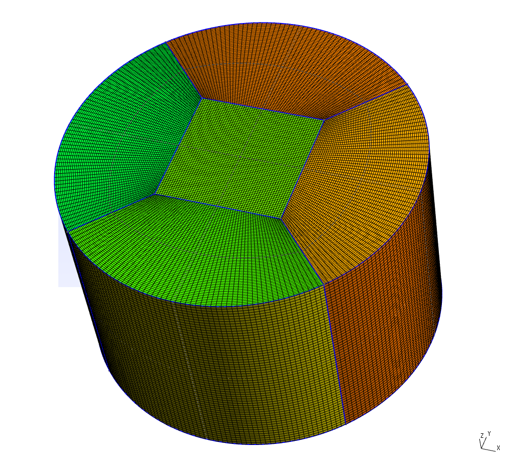
This time we'll convert the square into an octagon to gain control over additional points. Schematic top view of the cylinder subdivision will look like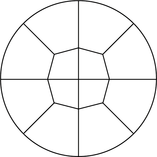
So in addition to 18 points of the first subdivision scheme we get 16 more points
Point(19) = {4.4505974153938341, 0, 0, 1.0};
Point(20) = {-4.4505974153938341, 0, 0, 1.0};
Point(21) = {0, 4.4505974153938341, 0, 1.0};
Point(22) = {0, -4.4505974153938341, 0, 1.0};
Point(23) = {4.4505974153938341, 0, 12.42, 1.0};
Point(24) = {-4.4505974153938341, 0, 12.42, 1.0};
Point(25) = {0, 4.4505974153938341, 12.42, 1.0};
Point(26) = {0, -4.4505974153938341, 12.42, 1.0};

Point(27) = {10, 0, 0, 1.0};
Point(28) = {-10, 0, 0, 1.0};
Point(29) = {0, 10, 0, 1.0};
Point(30) = {0, -10, 0, 1.0};
Point(31) = {10, 0, 12.42, 1.0};
Point(32) = {-10, 0, 12.42, 1.0};
Point(33) = {0, 10, 12.42, 1.0};
Point(34) = {0, -10, 12.42, 1.0};
Mesh looks like this
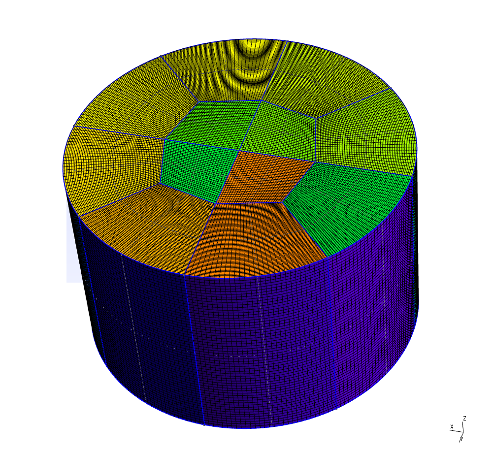
checkMesh output is show below and this will be the final version of the mesh.
Checking geometry...
    Overall domain bounding box (-10 -10 0) (10 10 12.42)
    Mesh (non-empty, non-wedge) directions (1 1 1)
    Mesh (non-empty) directions (1 1 1)
    Boundary openness (-5.92258e-17 1.42868e-16 1.79229e-15) OK.
    Max cell openness = 2.91797e-16 OK.
    Max aspect ratio = 3.98032 OK.
    Minimum face area = 0.00945675. Maximum face area = 0.0560611.  Face area magnitudes OK.
    Min volume = 0.00195755. Max volume = 0.00538261.  Total volume = 3901.38.  Cell volumes OK.
    Mesh non-orthogonality Max: 28.5444 average: 7.10033
    Non-orthogonality check OK.
    Face pyramids OK.
    Max skewness = 0.74746 OK.
    Coupled point location match (average 0) OK.

Mesh OK.
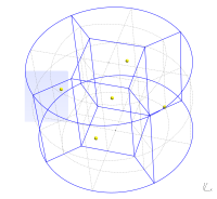
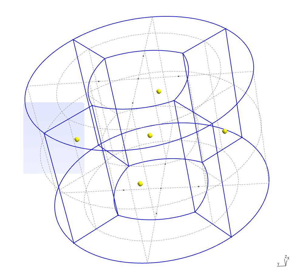
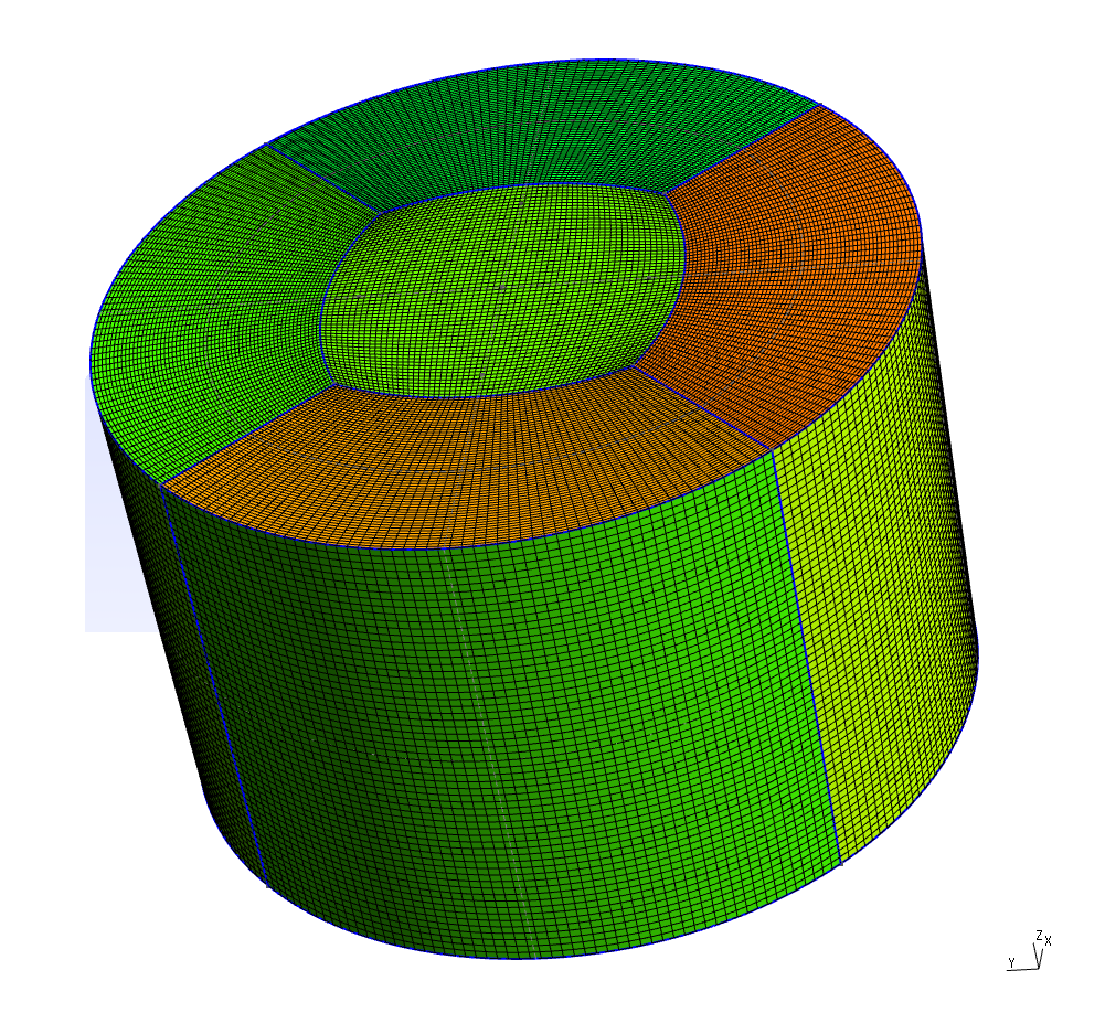
Spherical cap
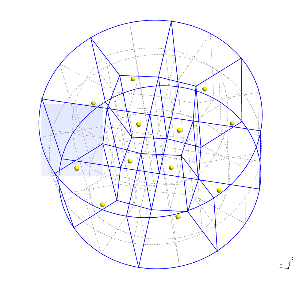
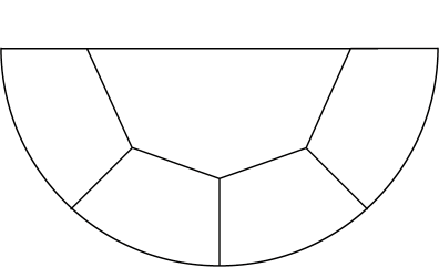
Spherical cap meshing is a further development of the last variant of cylinder mesh. Schematic top and center-plane cut views of the geometry decomposition are shown below, top view is the same as for cylinder and center-plane cut is almost the same as a half of top view.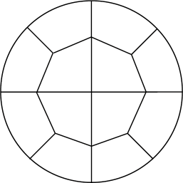
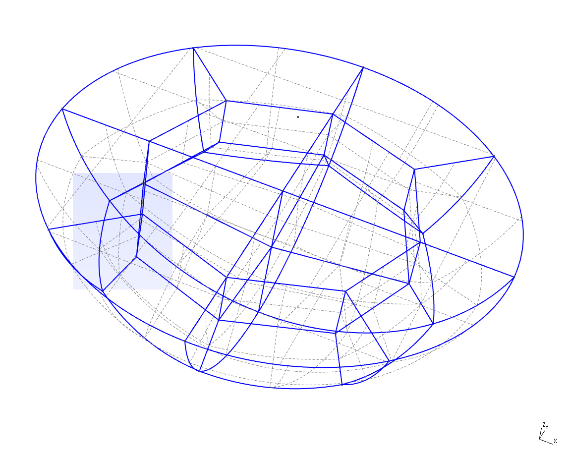
As the number of points in subdivision grows now it's easier to generate points programmatically than by hand. This is especially true for the points inside the cap and on "bottom" of the sphere. Still to connect points and to create the planes and the volumes one can use GUI (though it becomes less and less convenient). After these operations one get the following spherical cap decomposition into hexagonal volumes
In this case we have three sets of lines which can have different 1D mesh densities
density1 = 40;
density2 = 60;
density3 = 60;

// Vertical lines and arcs
Transfinite Line {122, 41, 42, 43, 44, 45, 46, 47, 48} = density1;
Transfinite Line {58, 59, 60, 61, 62, 63, 64, 65} = density1;

Transfinite Line {9, 10, 11, 14, 39, 30, 31, 32} = density2;
Transfinite Line {1, 2, 7, 12, 13, 17, 18, 6} = density2;
Transfinite Line {33, 34, 35, 36, 37, 38, 39, 40} = density2;
Transfinite Line {21, 22, 23, 24, 25, 26, 27, 28, 29} = density2;
Transfinite Line {66, 67, 68, 69, 70, 71, 72, 73} = density2;
Transfinite Line {74, 75, 76, 77} = density2;

Transfinite Line {49, 56, 16, 57, 15, 50, 8, 51} = density3;
Transfinite Line {4, 52, 3, 53, 5, 54, 19, 55, 20} = density3;

Transfinite Surface "*";
Recombine Surface "*";

Transfinite Volume "*";
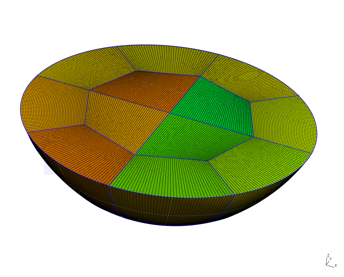
checkMesh report again indicates that we can improve our mesh, in general, it can be achieved by playing with points displacements in the top plane and especially by playing with the angles between octagonal cylindroid and points at the "bottom" of the cap.
Checking geometry...
    Overall domain bounding box (-6.25 -6.25 0) (6.25 6.25 4.4)
    Mesh (non-empty, non-wedge) directions (1 1 1)
    Mesh (non-empty) directions (1 1 1)
    Boundary openness (-5.1934e-17 -2.24174e-16 -3.86814e-15) OK.
    Max cell openness = 3.41873e-16 OK.
    Max aspect ratio = 3.10774 OK.
    Minimum face area = 0.000937704. Maximum face area = 0.00877925.  Face area magnitudes OK.
    Min volume = 3.14526e-05. Max volume = 0.000443903.  Total volume = 311.72.  Cell volumes OK.
    Mesh non-orthogonality Max: 46.0019 average: 13.8361
    Non-orthogonality check OK.
    Face pyramids OK.
    Max skewness = 0.714037 OK.
    Coupled point location match (average 0) OK.

Mesh OK.
Hello Alexey,
RépondreSupprimerI just stumbled across your blog. Great post comparing blockMesh and gmsh.
I recently came across gmsh while going through the following blog http://lordvon64.blogspot.in/2012/03/hybrid-structuredunstructured-meshing.html?showComment=1431612709648#c4326128210914448246.
I have written a gmsh file to create a hybrid mesh for a thin flat plate. I have 9 surfaces in the 2D mesh. I'm not sure how to handle them during extrusion since they are creating various edges i.e more than the usual front,top,bottom,inlet,outlet and wing.
Can you help me get past this problem? Here is the github link to the geo file -----> https://github.com/pruthvi1991/gmsh/tree/master/pilot .
Thanks,
Pruthvi.
Hello,
SupprimerUnfortunately I was not able to understand the question. Is it about definition of physical surfaces? You can open your geometry in Gmsh and then use GUI to create them.
Hi Alexey,
SupprimerTo capture the boundary layers I created a refined mesh near the wing surface. For the this I used the transfinite algorithm and I have 9 volumes in the mesh. These volumes intersect at internal faces. In OpenFOAM I don't know how to define these. When I left them undefined OpenFOAM named them as default faces.
defaultFaces
{
type patch;
nFaces 284;
startFace 562756;
}
I don't know how to handle these internal faces. Do you know how to handle this problem?
Here are some pictures to make it clear. https://drive.google.com/open?id=0B0O_EM6xOrebfm5FZE1TYUhqZXNUVlF2d1RfUUdxWU5KenJlbmV4dUN3dXUySnUyTG42WEk&authuser=0
Thanks,
Pruthvi.
1. I have tried to convert msh (created from your geo-file), was not successful. First there was higher-order elements, then wrong oriented prisms and finally gmshToFoam aborted with sigSegv.
Supprimer2. I still do not understand your problem.
3. I still do not understand what you are trying to achieve.
4. You was not able to interest me enough to look for the errors in your geo-file.
Try Gmsh mailing list or forums on cfd-online.com.
ok thanks for the effort. I was able to convert without any such issues. I just updated the geo file by adding some physical surfaces and volumes but it shouldn't matter in the conversion.
Supprimer"Inverting prism 147798" ------> Is this what you mean by wrong oriented prism?
I'm just trying to achieve a nice hybrid mesh for a pitching and plunging airfoil. If you have the time to look into this problem again, please do a git pull. There might have been some issues with the previous .geo file.
I was able to fix the problem. The issue was caused by a non-conformal region. Thanks for your effort.
SupprimerI downloaded 'Cylinder-3.geo' and then simply clicked 'Mesh 3D'.
RépondreSupprimerI get a mesh with appr. one million cells.
How can I change this? I tried with 'Element size at points' - no effect.
Mikko
As mesh is generated using transfinite algorithm, 'Element size at point' really does not affect density of the mesh. Number of cells can be adjusted by modifying settings on lines 257-265 (https://bitbucket.org/mrklein/gmsh-meshing/src/db90a5048eb18c047eb98f2cf5b6c3eb283e45b2/cylinder-3.geo?at=default#cl-257). On lines 257-258 number of vertical cells is set (in fact number points on vertical lines, so it is number of cells + 1). Lines 259-260 control number of cells in radial direction in outer blocks. Finally lines 261-265 control subdivision of inner blocks and subdivision of outer block in azimuthal direction (and these values should be equal as lines are opposite of each other).
SupprimerMany thanks for your prompt advice.
SupprimerI will just look more carefully at the geometry to understand clearly which geometry line is which in those 'Transfinite Line' rules.
Now that is setting the number of points, and they will be equally spaced. Is it possible to set exact locations of points on the geometry lines? I would make the mesh denser at interesting places.
I am going to generate the .geo files by a separate code (like in the 'Spherical cap' example); I will do it in Matlab or C which I used more than Python.
Can I generate the meshes from the .geo files by batch running gmsh as command line tool?
I am a new user to gmsh, but it looks like a very nice tool at least for simple cases. More complicated geometries - that remains to be tried.
Mikko
I do not know how to set exact locations of the points in transfinite algorithm. If you would like to have dense mesh in certain regions you can use "Using Progression" or "Using Bump" options. See http://www.geuz.org/gmsh/doc/texinfo/gmsh.html#Structured-grids.
SupprimerYou can use it like "gmsh file.geo -3 -o mesh.msh", or "gmsh - file.geo" (in this case you add "Mesh 3; Save "mesh.msh";" in the file.geo). See http://www.geuz.org/gmsh/doc/texinfo/gmsh.html#Non_002dinteractive-mode.
I tried to write a CGNS file, but got: Error. This version was compiled without CGNS support.
SupprimerIs it possible to have a version with CGNS?
Do you know if a Paraview reader exists for the *.msh mesh files?
Mikko
Yes, it is possible to have version with CGNS support. Just compile it.
SupprimerNever tried to open MSH file with Paraview (as for my use-cases MSH file are just mesh files). According to Google there were attempts to write such reader.
Hi Alexey, thanks for your tutorial! I have a gmsh script which creates a 2D airfoil cascade mesh. The boundary layer is meshed in hexagonal elements and everything else is tetrahedra. The only thing that I can't seem to get to work is mesh refinement of the trailing edge. Would it be possible for you to look at my script?
RépondreSupprimerSure I can look at your script. Create Gist (or something similar, or even create repository, so discussion can happen in Issue tracker), post link.
SupprimerAlso if you are meshing 2D airfoil, did you try Construct2D (https://sourceforge.net/projects/construct2d/)?
Thanks! Please see https://github.com/Quadrupole/airfoil2D. Basically my issue is now trying to get a good way to have natural refinement at the leading and trailing edges and a coarser mesh nearer the mid chord. I want a smooth transition between these two regions but the Bump and Progression methods of the Transfinite lines don't seem to offer this. It should be apparent from running the script. Let me know if there are any questions.
RépondreSupprimerActually I realised that I need Hyperbolic extrusion in the boundary layer - something like http://www.pointwise.com/DIY/Extruding-Structured-Domain-Out-of-Airfoil.shtml
RépondreSupprimerBecause I will always have the problem of the mesh becoming 'stretched' near the leading and trailing edge curvature. I am not sure if GMSH can handle that easily? I see that construct2d has this feature, but do you have any experience or knowledge of whether it can create a cascade geometry (where the there are two periodic boundaries above and below the airfoil)?
My experience with Construct2d is limited to: oh, it makes nice meshes, much better than ones I have tried to make with Gmsh ;) Since it was just for fun, I never went below default mesh generation settings.
SupprimerI see! Well hopefully GMSH will add hyperbolic extrusion options for structured meshing! It would be nice to have for these purposes. Thanks for having a look!
SupprimerCe commentaire a été supprimé par l'auteur.
RépondreSupprimerThe script is now updated to something that looks ok (at least for solving RANS). However I have some trouble importing to openFoam (the conversion gmshToFoam works fine) but when I run the simulation I get --> FOAM FATAL IO ERROR:
RépondreSupprimersize 12216 is not equal to the given value of 30962. I have added the openFoam case to the repo. I would greatly appreciate if you could have a look as I think the error is caused by improper number of cells being specified, possible related to the way I define my volume in GMSH.
You have internal field in 0/U for smaller mesh. Your current mesh:
SupprimerMesh stats
...
cells: 30962
in 0/U
...
internalField nonuniform List
12216
...
Ah thats so stupid of me I had forgotten the file was copied from another case... Thanks for taking a look!
SupprimerHi again Alexey - I have found that my mesh created as in the above example gives me incorrect results in OpenFoam and I believe it could be due to the mesh. When I tried the same case with a hyperbolic extruded boundary layer mesh I get the expected results. I am therefore wondering if you think it could be possible to mesh the blade in construct2D, export to GMSH and then "fill" in the region between the boundary layer hex grid and the periodic boundaries.
RépondreSupprimerHi,
SupprimerThis is how I imagine this:
1. Generate airfoil mesh with Construct2D, it outputs mesh in p3d format. Since later you want to use it with OpenFOAM, general 3D mesh with 2 planes (see OOPT menu).
2. Convert mesh to Gmsh format. Obviously, I used p3d2gmsh.py (https://github.com/mrklein/p3d2gmsh). For naca2315 Construct2D generated mesh with two ONE-TO-ONE boundaries, so they should be stitched later (names of the patches *-to-stitch-*).
3. Generate mesh with periodic boundaries and a hole in the centre, where you put mesh generated with Construct2D (as a separate case).
4. Use mergeMesh to merge meshes.
5. Use stitchMesh to stitch extra-boundaries.
Unfortunately I have performed only steps 1 and 2 (and there are no problems), there could be certain difficulties during steps 3-5.
Ok thanks ill try that. I agree the only difficulty I see is getting the right matching between the points from the GMSH and that of construct2D. Let's see how it pans out!
SupprimerCe commentaire a été supprimé par l'auteur.
RépondreSupprimerHi Alexey,
RépondreSupprimerI have gone through your examples above and have found them really useful. Thank you very much for sharing them! I have got a problem when we specify the grades for bump since it doesn’t seem to be straightforward like progression. I have checked the source code and found the formula that does the calculation. However, when I did a simple test by providing values for the number of points, length as well as coef, the result doesn’t match what gmsh provided. I was wondering if you know how to calculate grades when using the bump in Gmsh. The formula for bump function in Gmsh is as follows;
case 2: // Bump
{
double a;
if(coef > 1.0) {
a = -4. * sqrt(coef - 1.) * atan2(1., sqrt(coef - 1.)) /
((double)nbpt * length);
}
else {
a = 2. * sqrt(1. - coef) * log(fabs((1. + 1. / sqrt(1. - coef)) /
(1. - 1. / sqrt(1. - coef))))
/ ((double)nbpt * length);
}
double b = -a * length * length / (4. * (coef - 1.));
val = d / (-a * SQU(t * length - (length) * 0.5) + b);
}
I would really appreciate any clarifications.
Thank you very much.
Hi,
SupprimerIt is much easier to get answer from authors of the software (Gmsh has its own mailing list). Quick Google search reveals the following:
http://onelab.info/pipermail/gmsh/2008/003526.html
Quite detailed explanation from Christophe Geuzaine.
Thanks for the reply. The previous page that you sent is for progression in one side using the layer command. However, for bump, progression in both sides, I could not get the same node distributions using the following ad hoc function;
RépondreSupprimercase 2: // Bump
{
double a;
if(coef > 1.0) {
a = -4. * sqrt(coef - 1.) * atan2(1., sqrt(coef - 1.)) /
((double)nbpt * length);
}
else {
a = 2. * sqrt(1. - coef) * log(fabs((1. + 1. / sqrt(1. - coef)) /
(1. - 1. / sqrt(1. - coef))))
/ ((double)nbpt * length);
}
double b = -a * length * length / (4. * (coef - 1.));
val = d / (-a * SQU(t * length - (length) * 0.5) + b);
}
I tried everything but nothing is working. How do you usually get the node distribution using bump?
Thank you very much.