This post appeared due to the question on
cfd-online.com OpenFOAM forum. It has been started as yet another post on
Kármán vortex street but then (
around message #60) original poster revealed an article he was trying to compare with, so I've decided to check influence of different discretisation schemes and convergence criterions on final results.
Geometry and flow conditions
The first version of geometry and boundary conditions can be found in
post #11, though they slightly differ from the geometry provided in the article (and as a result, from geometry used in simulations).
So we've got a cylinder with diameter D placed in the channel with a length 16D and a width 8D. At the inlet we have velocity 1 m/s, at the outlet zero pressure and zero gradient in velocity. Initially velocity inside the domain set to 1 m/s. With D = 1 m and fluid kinematic viscosity 100 m2/s, Reynolds number is equal to 100.
First attempt
Well, the first variant of the simulation was just a simulation for its own sake (even Re was 200). Just to produce neat pictures. And these videos:
Flow develops, vortices go.
Second attempt
After reading the original article I've decided to check different meshes, discretisation schemes, and convergence criteria to learn if there's any difference. In the article authors were developing new method in FEM framework, so theirs original mesh was triangular with increased density near a centerline of the channel. Now I think there's a need for another set of simulations: with and without increase of mesh density near the center-line of the channel.
Meshes
I've fallen in love with
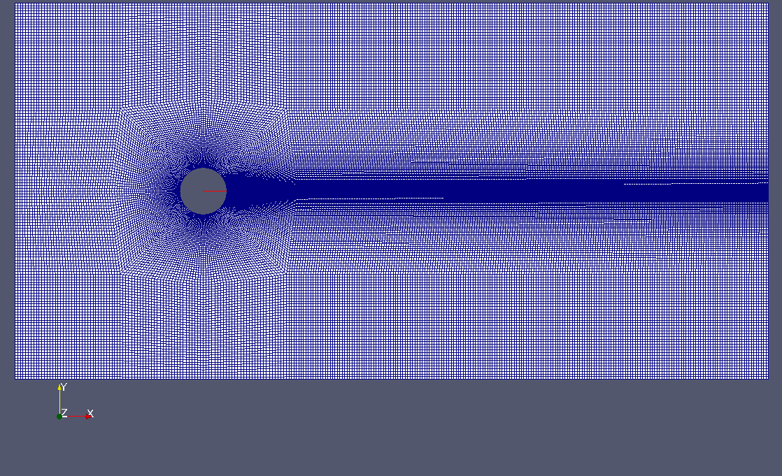
Gmsh for generating meshes, so these two meshed are produced with it. As Gmsh now has transfinite algorithm, it is more or less like blockMesh with GUI, variables and functions in a mesh file, more convenient way of grading description. Much like in blockMesh one needs to define vertices and then can use GUI to describe lines, surfaces and volumes. Then again switch to text editor for definition of transfinite lines, progressions (in the sense of Gmsh), etc. I will omit iterations during the mesh creation process and just provide GEO files with screenshots of the mesh:
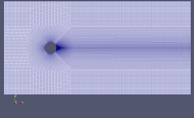
"Coarse" mesh
 Coarse cylinder-2D.geo
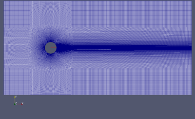
"Fine" mesh
 Fine cylinder-2D.geo
The only difference between coarse and fine mesh is twice increased density in case of "Fine" mesh. So a number of cells in the fine mesh is 4 times higher than in coarse mesh.
fvSchemes
Typical fvSchemes file is provided below. The only line that is changed from simulation to simulation is
div(phi,U) Gauss vanLeerV;, I've chosen to compare three different second order discretisation schemes with limiters: van Leer, QUICK, and Gamma.
/*--------------------------------*- C++ -*----------------------------------*\
| =========                 |                                                 |
| \\      /  F ield         | OpenFOAM: The Open Source CFD Toolbox           |
|  \\    /   O peration     | Version:  1.6                                   |
|   \\  /    A nd           | Web:      www.OpenFOAM.org                      |
|    \\/     M anipulation  |                                                 |
\*---------------------------------------------------------------------------*/
FoamFile
{
   version     2.0;
   format      ascii;
   class       dictionary;
   location    "system";
   object      fvSchemes;
}
// * * * * * * * * * * * * * * * * * * * * * * * * * * * * * * * * * * * * * //

ddtSchemes
{
   default         CrankNicolson 1.0;
}

gradSchemes
{
   default         Gauss linear;
}

divSchemes
{
   default         none;
   div(phi,U)      Gauss vanLeerV;
   div((nuEff*dev(T(grad(U))))) Gauss linear;
}

laplacianSchemes
{
   default         none;
   laplacian(nuEff,U) Gauss linear corrected;
   laplacian((1|A(U)),p) Gauss linear corrected;
}

interpolationSchemes
{
   default         linear;
}

snGradSchemes
{
   default         corrected;
}

fluxRequired
{
   default         no;
   p               ;
}


// ************************************************************************* //
fvSolution
In case of fvSolution file I changed
PIMPLE dictionary:
PIMPLE
{
    momentumPredictor yes;
    nCorrectors       2;
    nOuterCorrectors  20;
    nNonOrthogonalCorrectors 1;

    residualControl
    {
        "(U|p)"
        {
            tolerance 1e-2;
            relTol 0;
        }
    }
}
Keeping everything else the same, I changed tolerance in
residualControl dictionary to see if it influence results. I've checked values 1e-2, 1e-4, and 1e-6. This value defines the moment when PIMPLE loop will exit from outer corrector cycle. And usually in the beginning of a simulation number of outer correctors is around 4 (for the case of residual 1e-6 - 8), during the time this number falls to 2 (or 4 for the case of 1e-6). I don't know why all tutorial cases use fixed number of outer corrector iterations, sometimes it can lead to completely incorrect results. Maybe OpenFOAM decided that residualControl is "advanced" technique.
Also there're lots of scary posts on relaxation, so I've decided also to check the influence of relaxation factors on results of a simulation. So instead of standard
relaxationFactors
{
    fields
    {
    }
    equations
    {
       "U.*" 1.0;
       "p.*" 1.0;
    }
}
I used
relaxationFactors
{
    fields
    {
    }
    equations
    {
       "U.*" 0.7;
       "p.*" 0.3;
    }
}
Results
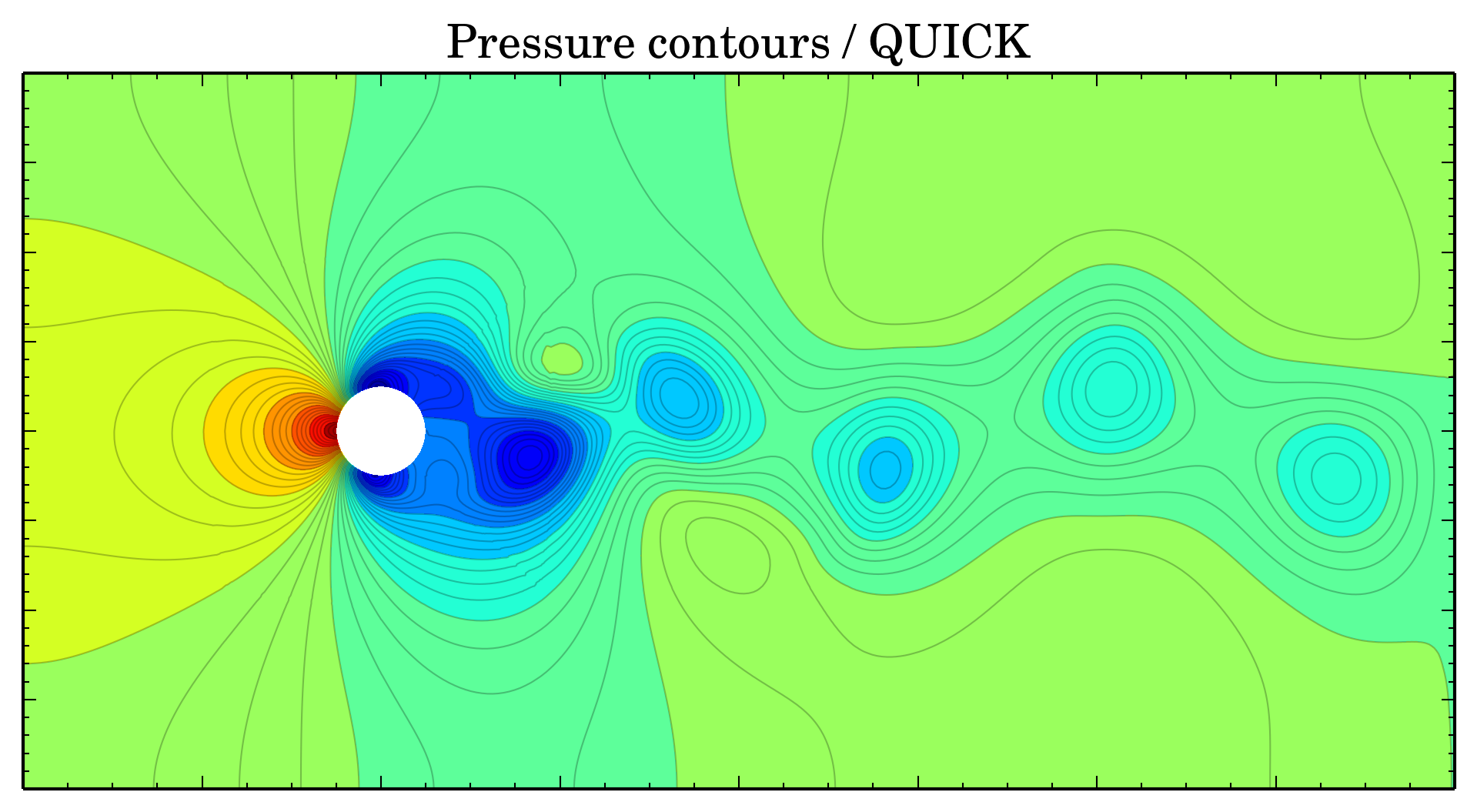
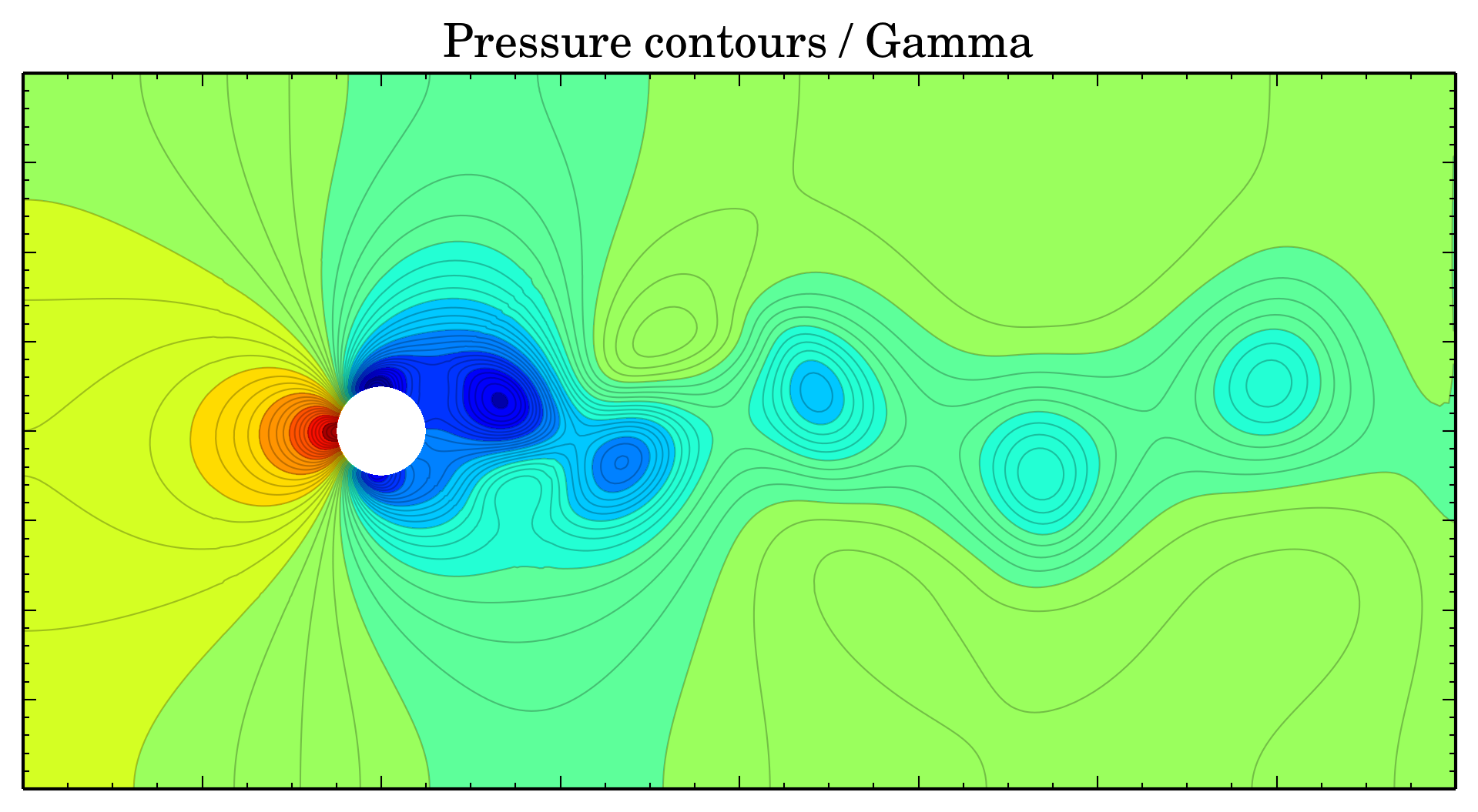
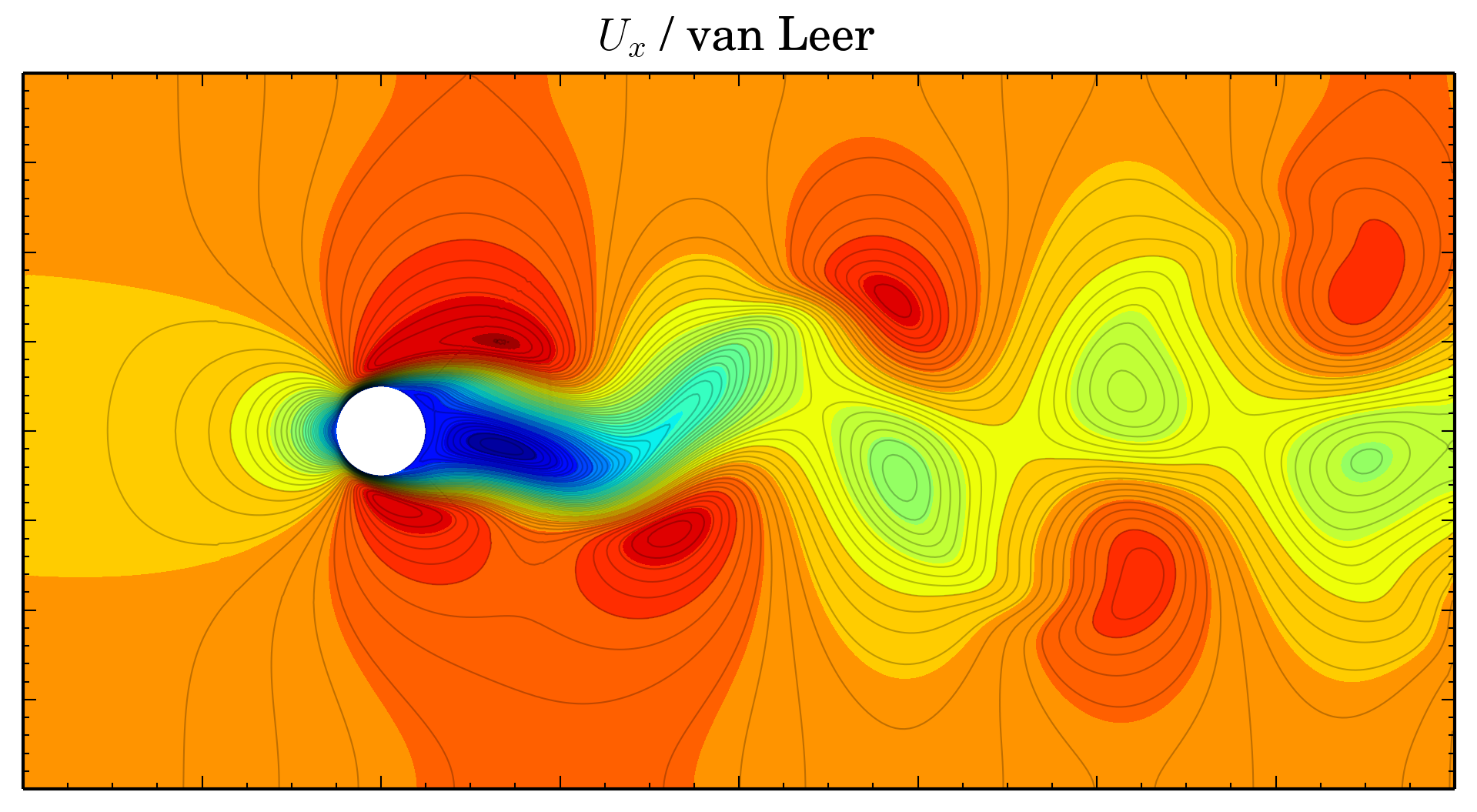
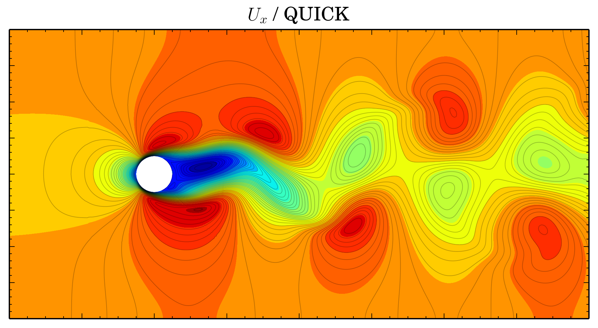
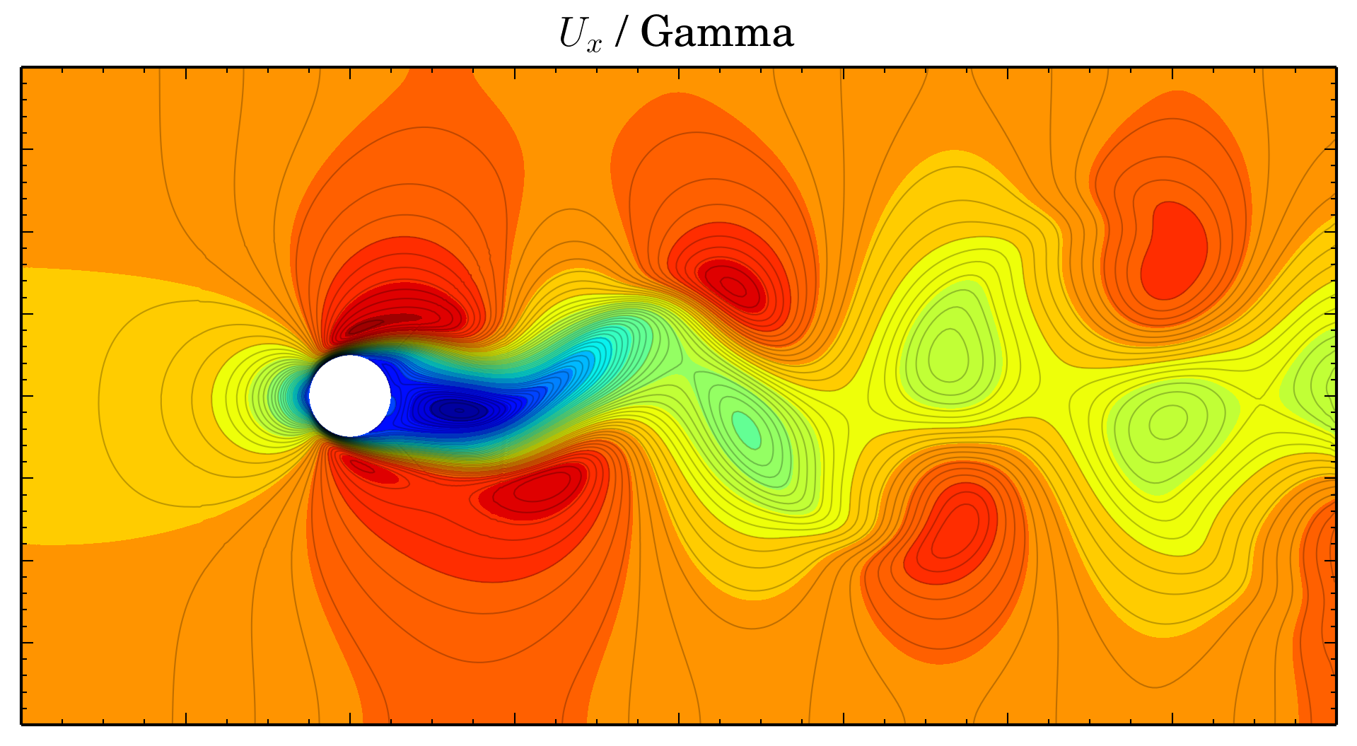
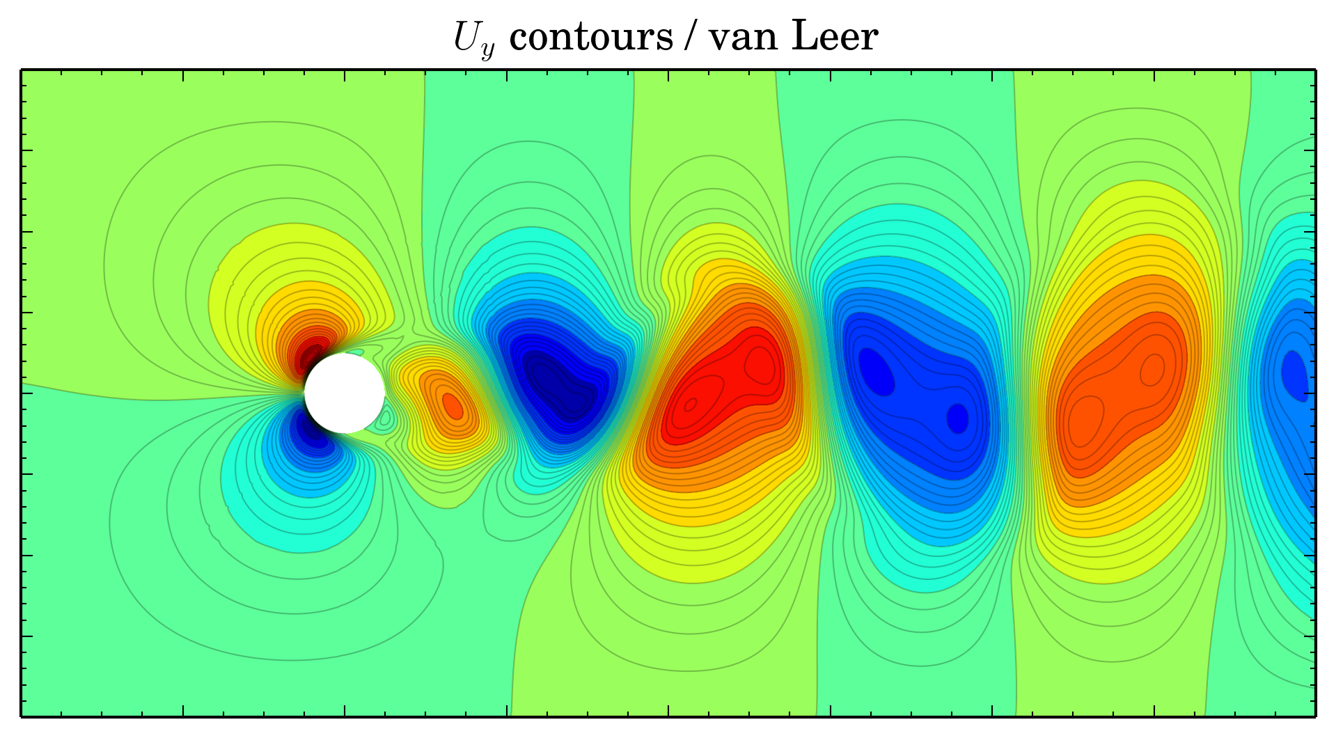
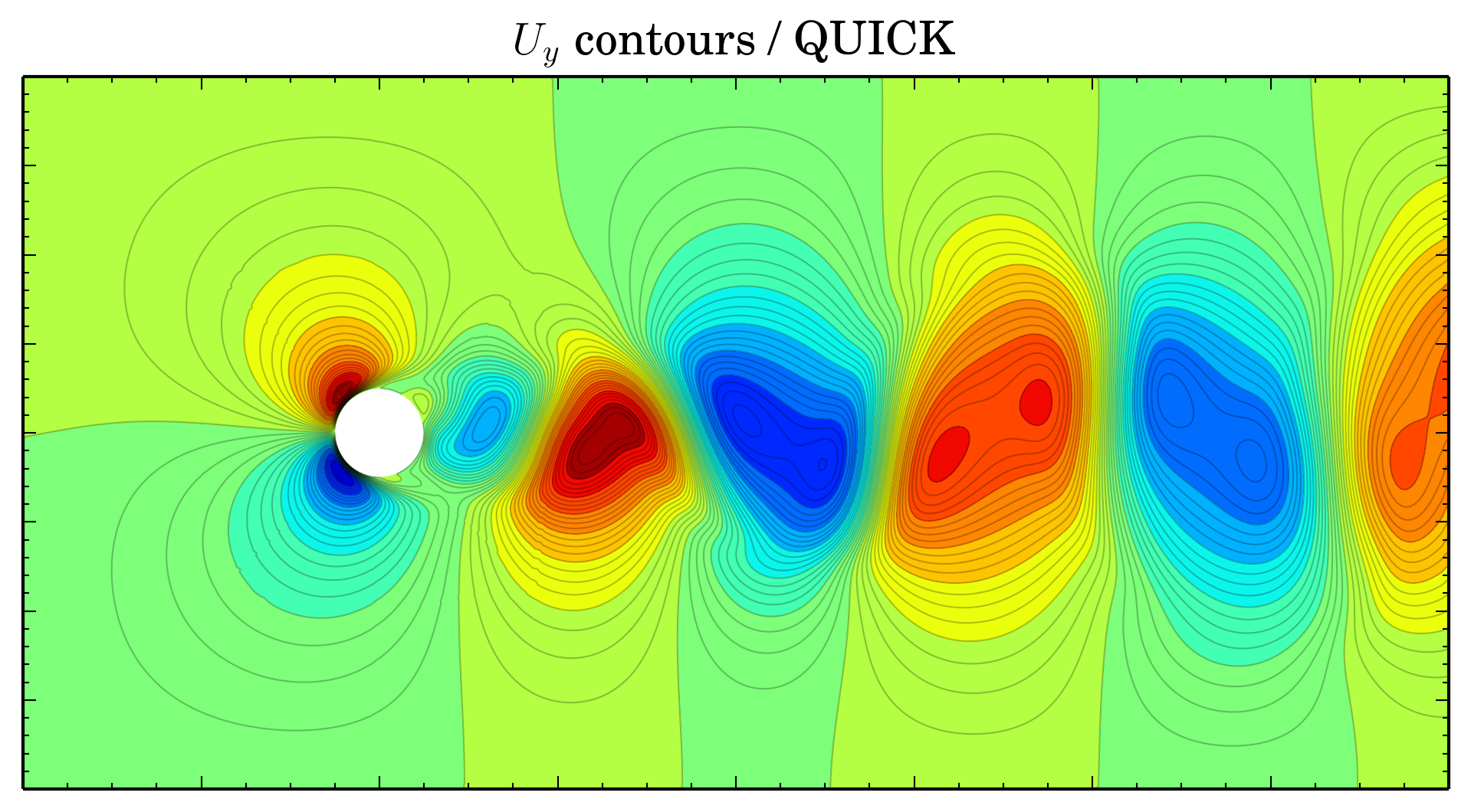
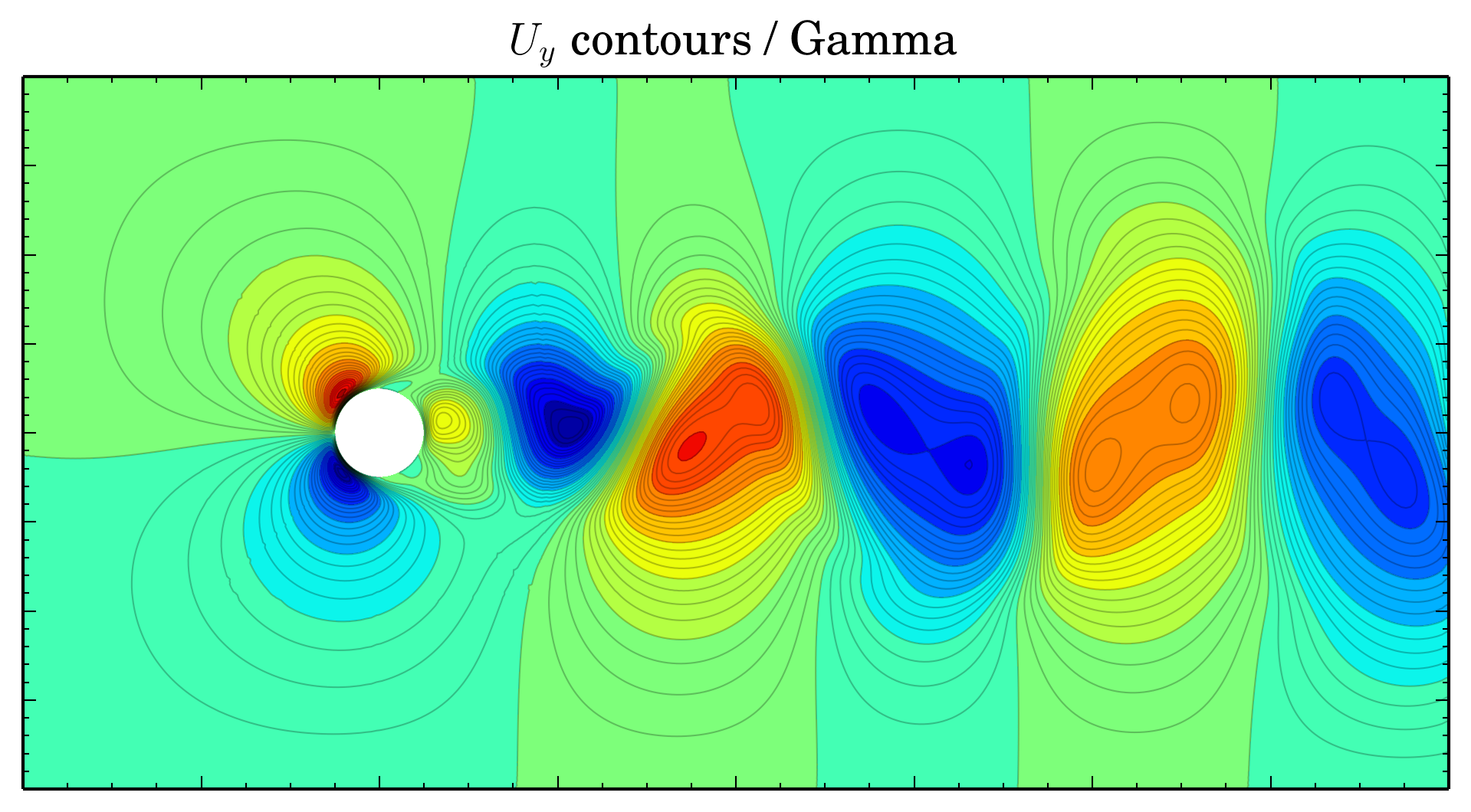
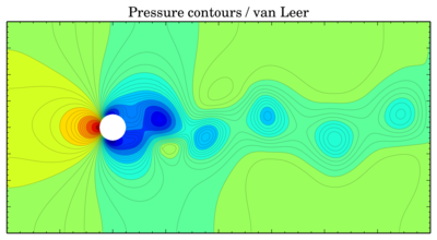
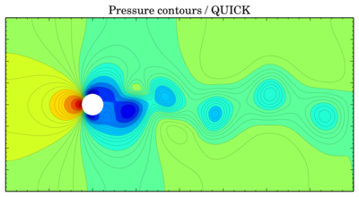
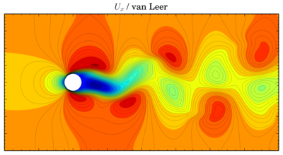
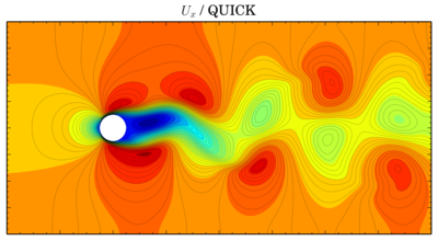
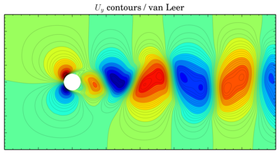
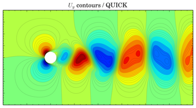
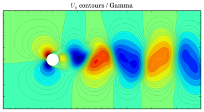
Color contours usually provide only schematic view of the flow, so further (surely after these pictures) I will be comparing oscillations of force coefficients. Sometimes it is possible to plot isolines of pressure and velocity on the same picture (when the phases of the oscillating flow do not differ much). But now, the color contours (time is 150 s):
Pressure
van Leer
 QUICK
QUICK
 Gamma
Gamma
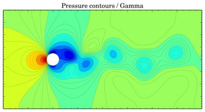
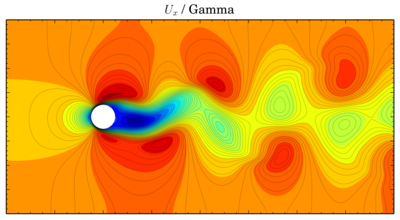
Though values seem to be more or less the same, vortices are shifted in time. The same thing is for velocity components:
Ux
van Leer
 QUICK
QUICK
 Gamma
Gamma
 Uy
van Leer
Uy
van Leer
 QUICK
QUICK
 Gamma
Gamma
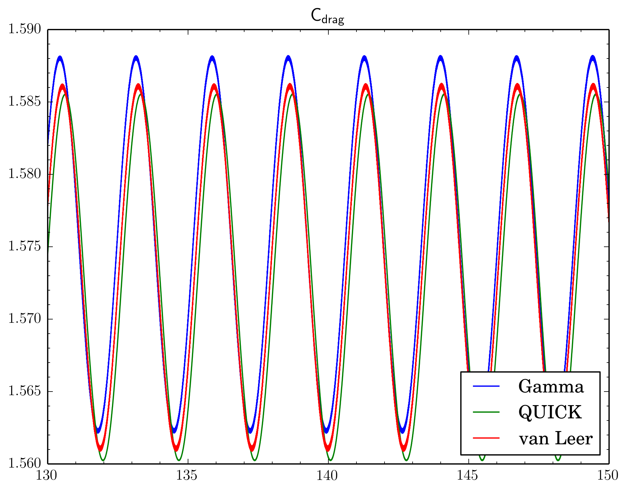
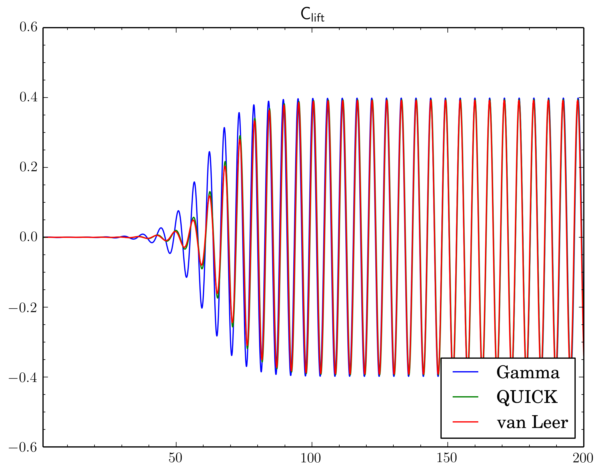
Discretisation schemes comparison
I've fixed final residual in
fvSolution at 1e-6 and just changed discretisation scheme. On the graphs X-axis is time, Y-axis is value. All simulations were done on the 'fine' mesh.
There is phase shift between graphs, I've moved them to compare oscillation amplitude. There is difference but it's not so big.
And as there is phase shift between different scheme I will omit comparison of the pressure and velocity contours. While there is difference between Cdrag oscillation amplitudes, Clift oscillations go rather synchronously:
Final residuals comparison
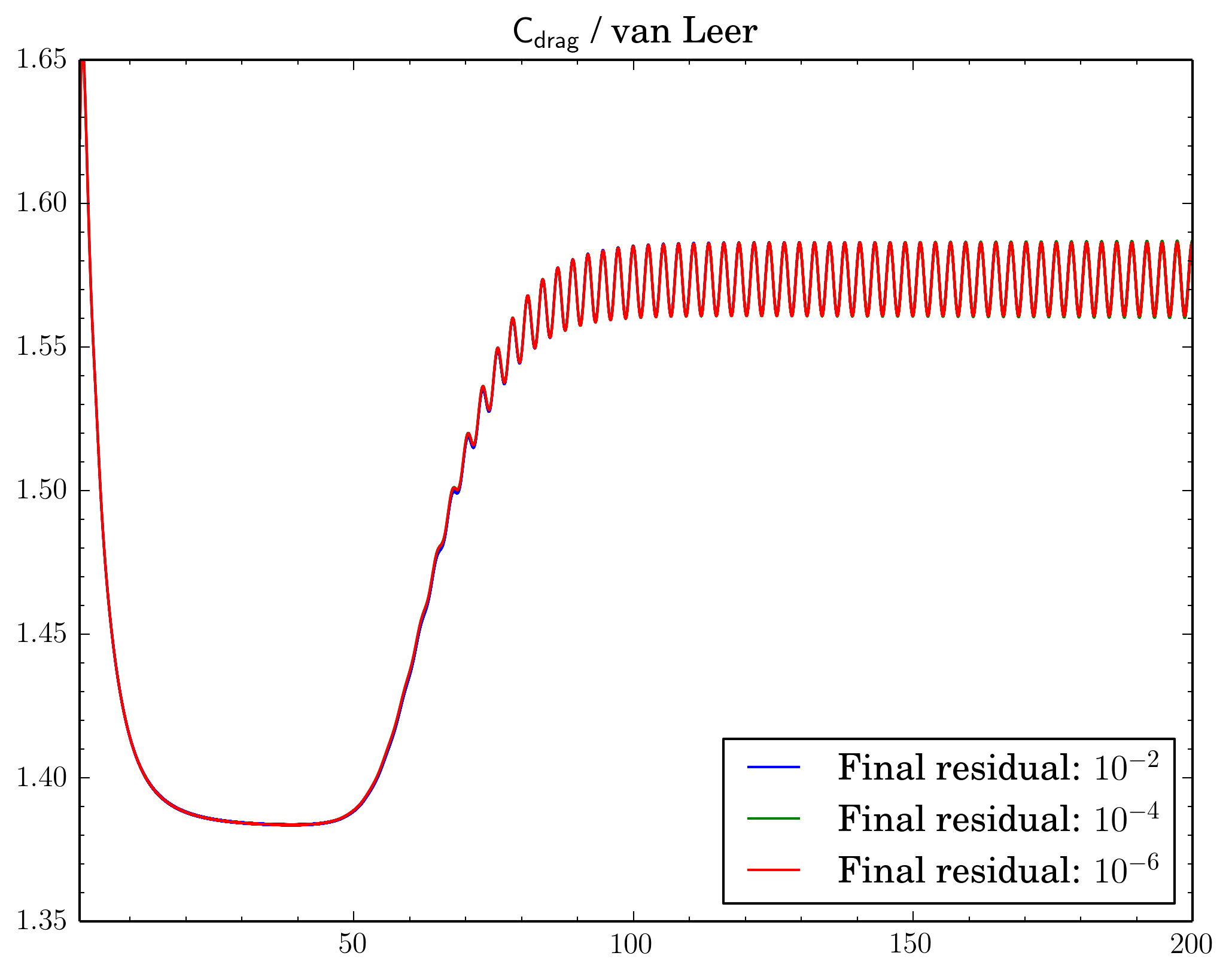
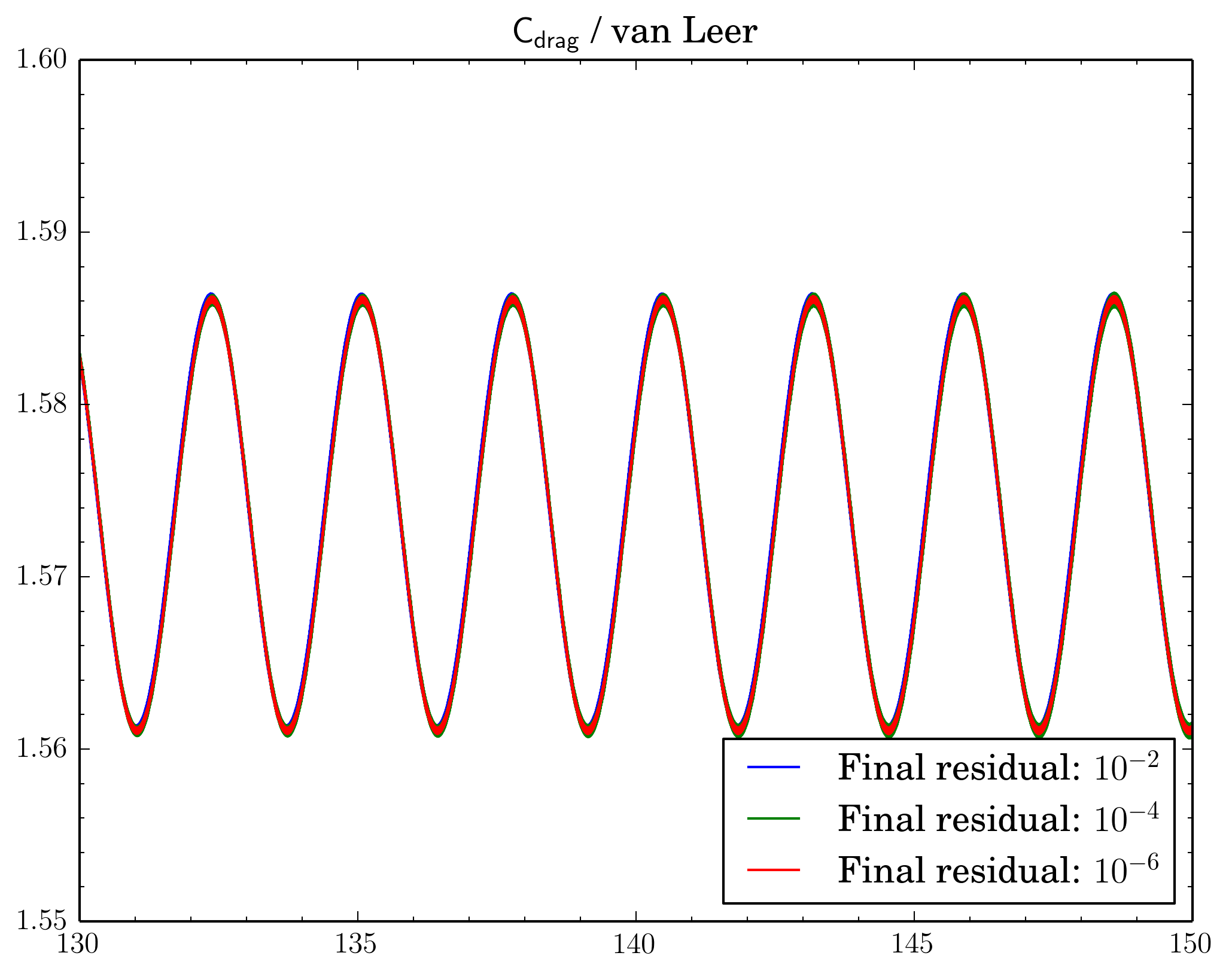
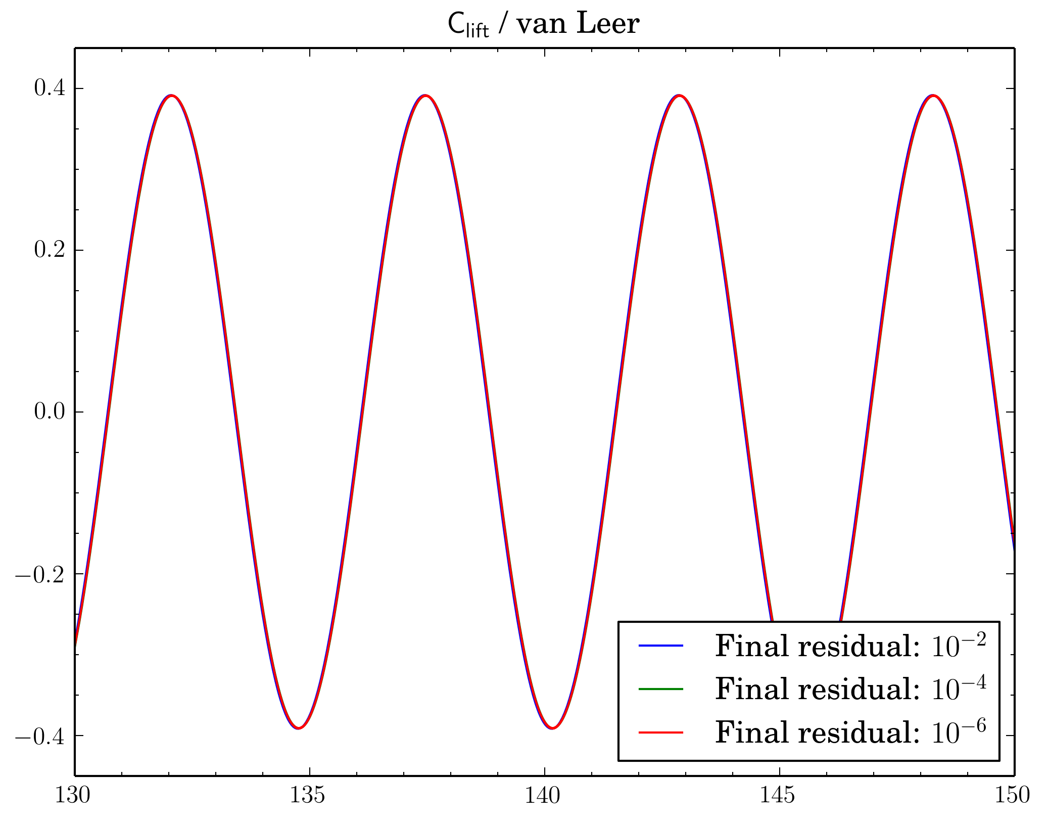
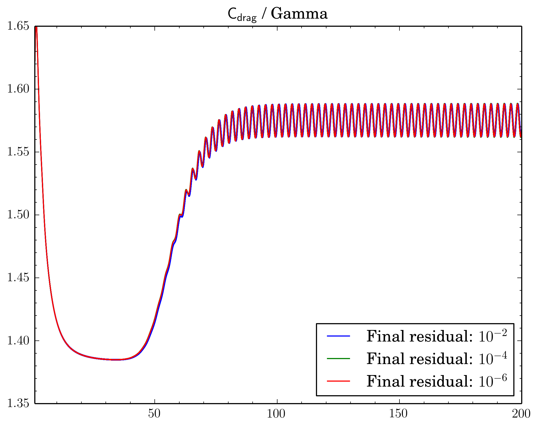
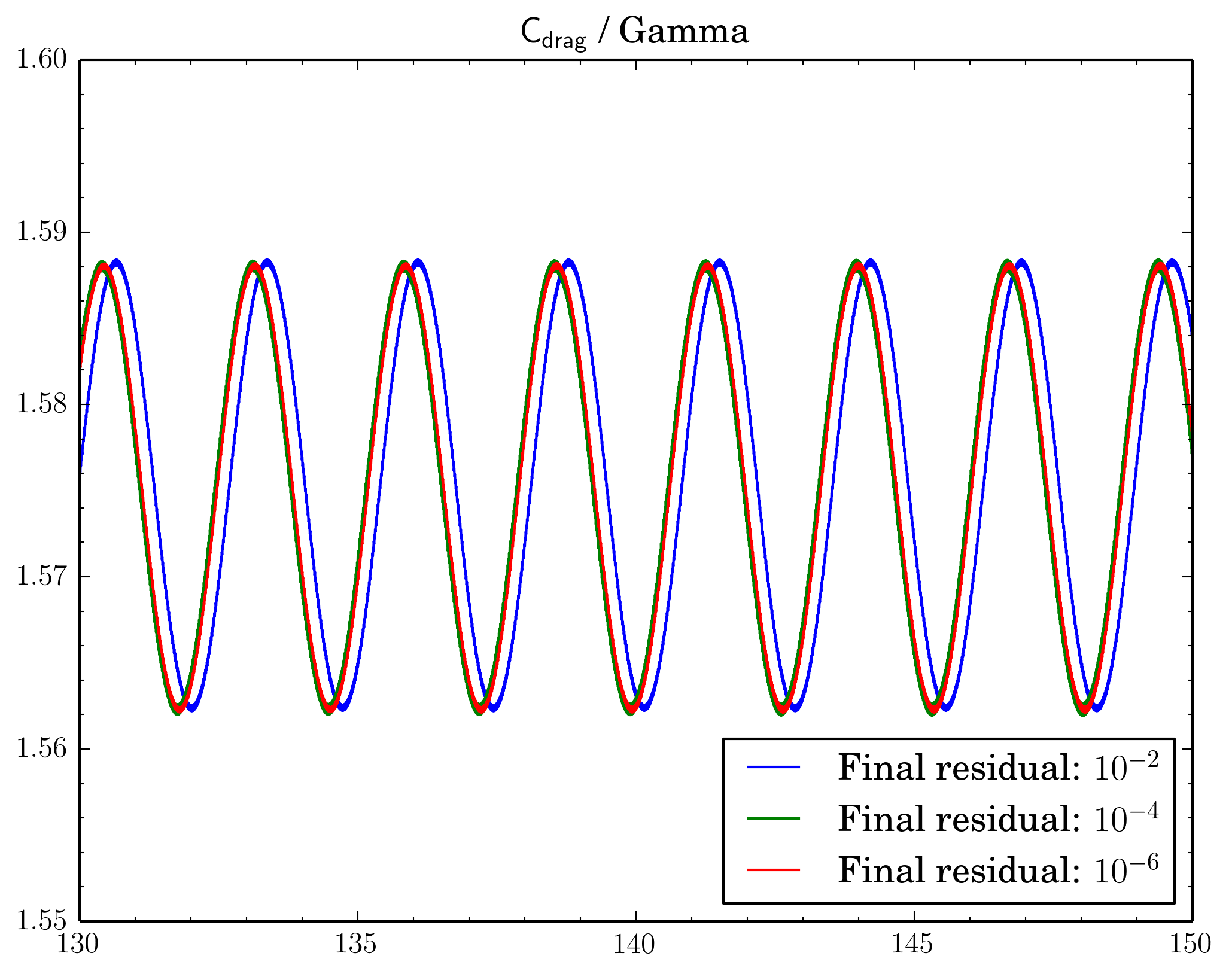
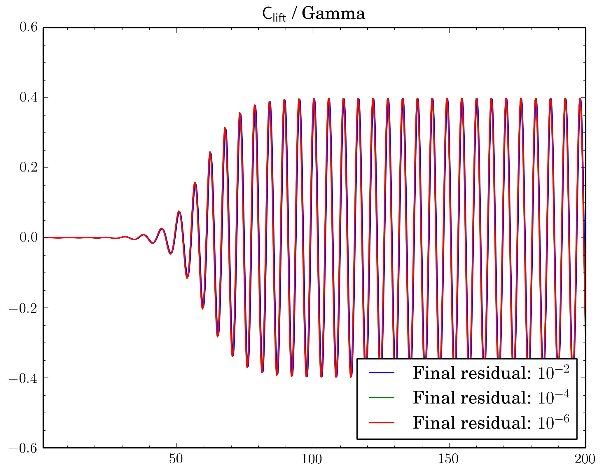
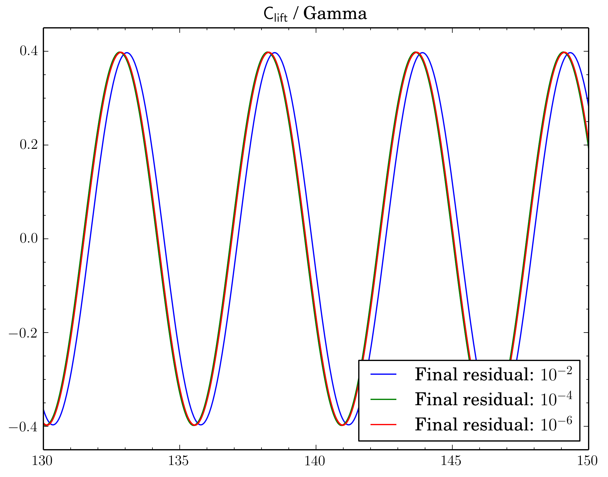
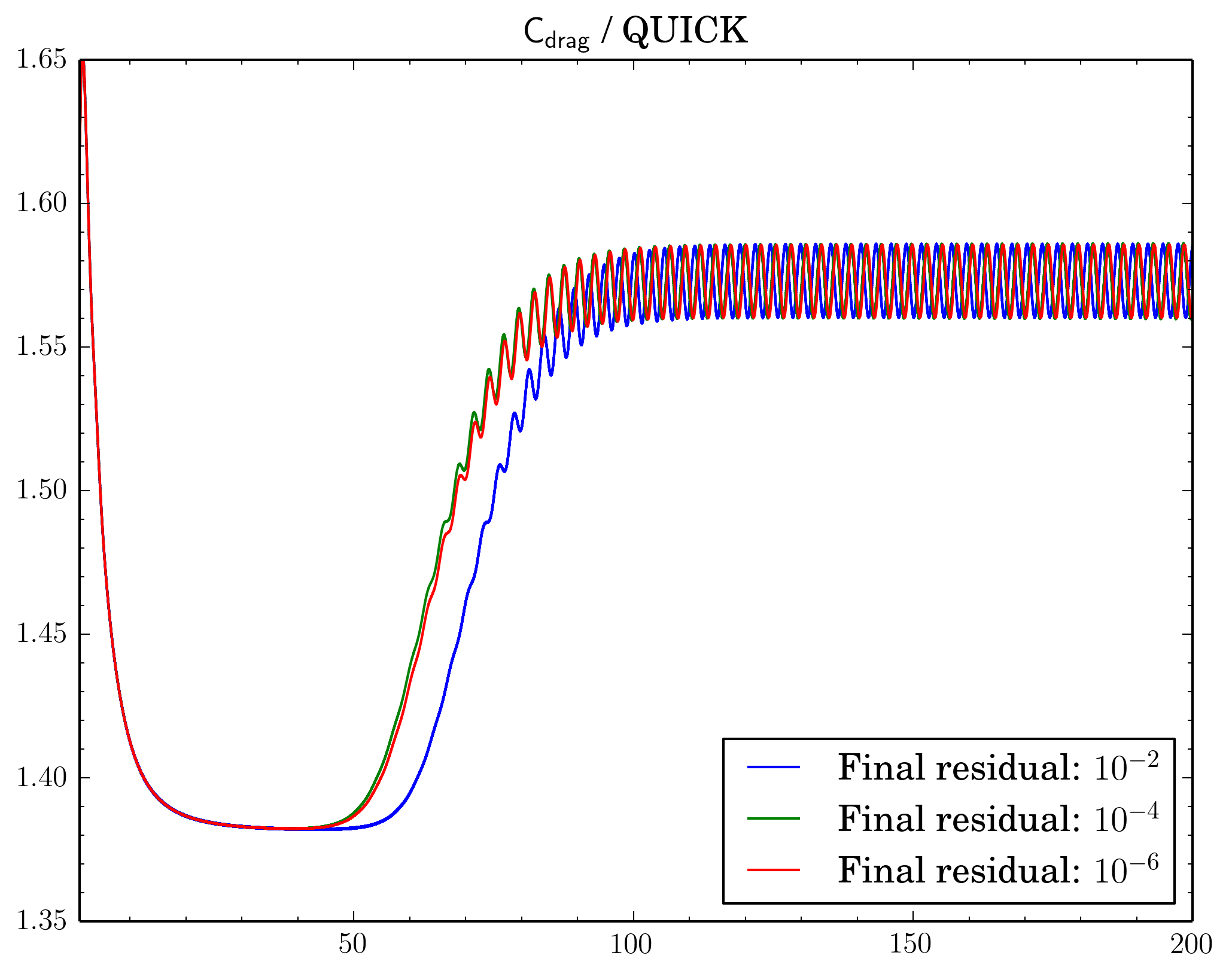
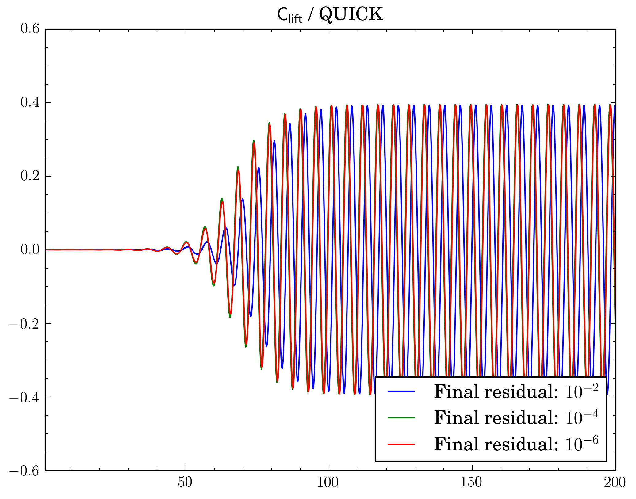
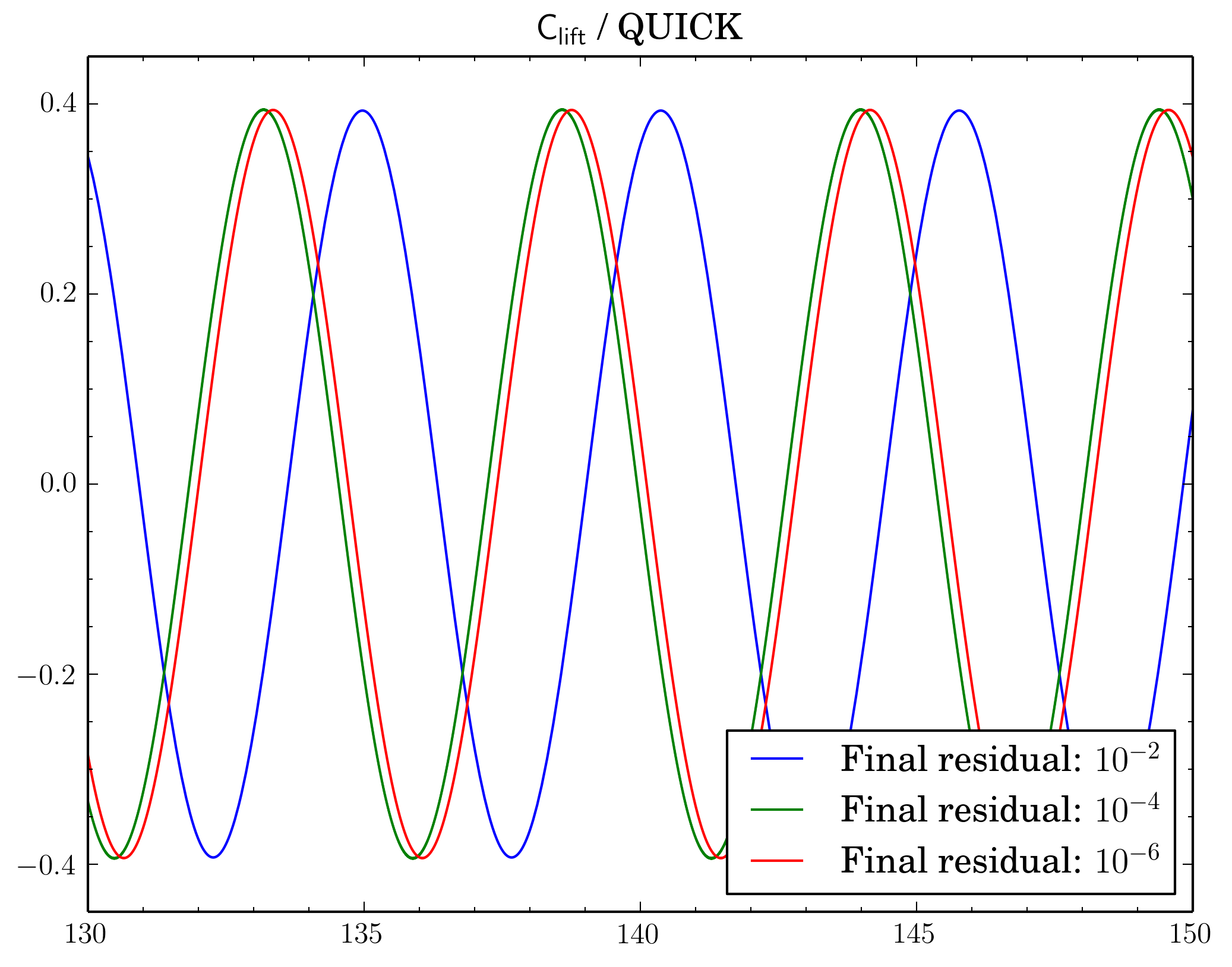
After that I've decided to check sensitivity of a discretisation scheme on final residual. I've fixed the scheme and run simulations for different final residuals: 1e-2, 1e-4, and 1e-6.
While van Leer and Gamma showed almost no dependence (though there is slight shift when going from 1e-2 to 1e-4 for Gamma):
For QUICK switch from 1e-2 to 1e-4 leads to quite large time shift between oscillations:
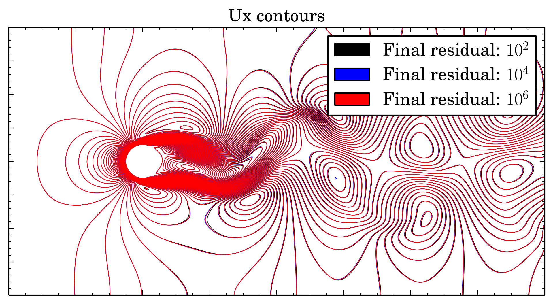
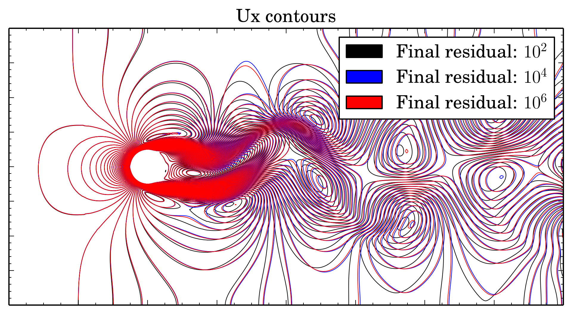
But even if the time shift in oscillations seems to be not so big, positions of the vortices are strongly depend on this shift. Below is overlays of Ux isolines for van Leer and Gamma schemes at 150 s:
If for van Leer scheme contours are almost the same, for Gamma results with residual 1e-2 are sufficiently shifted.
Mesh density comparison
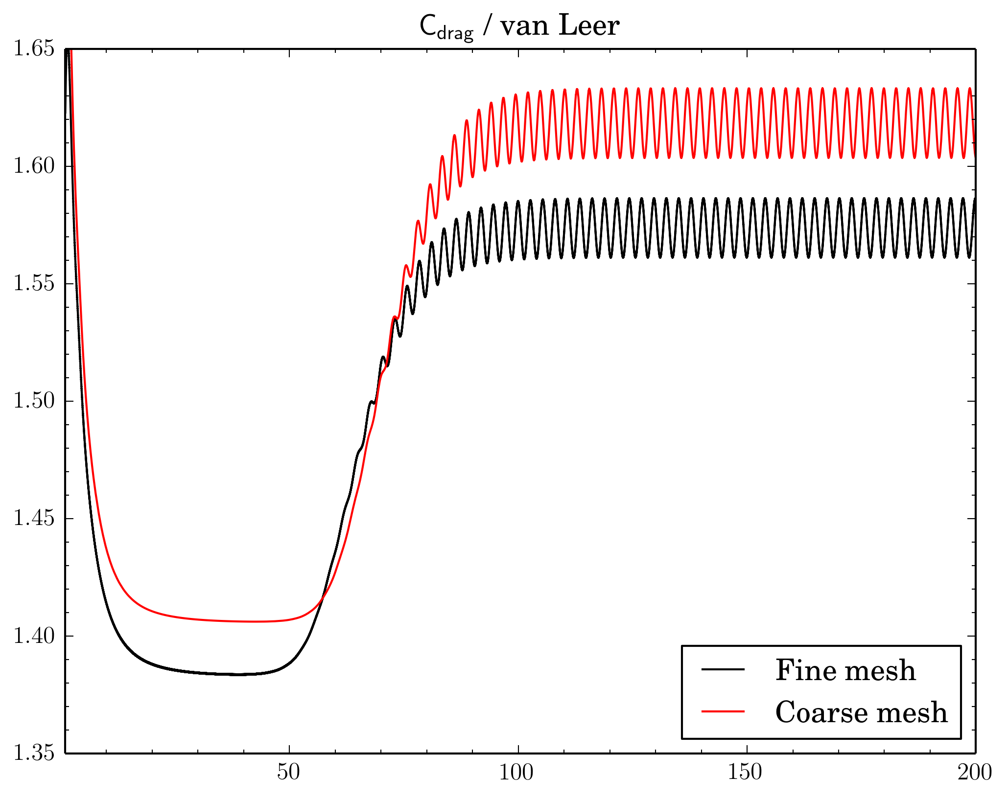
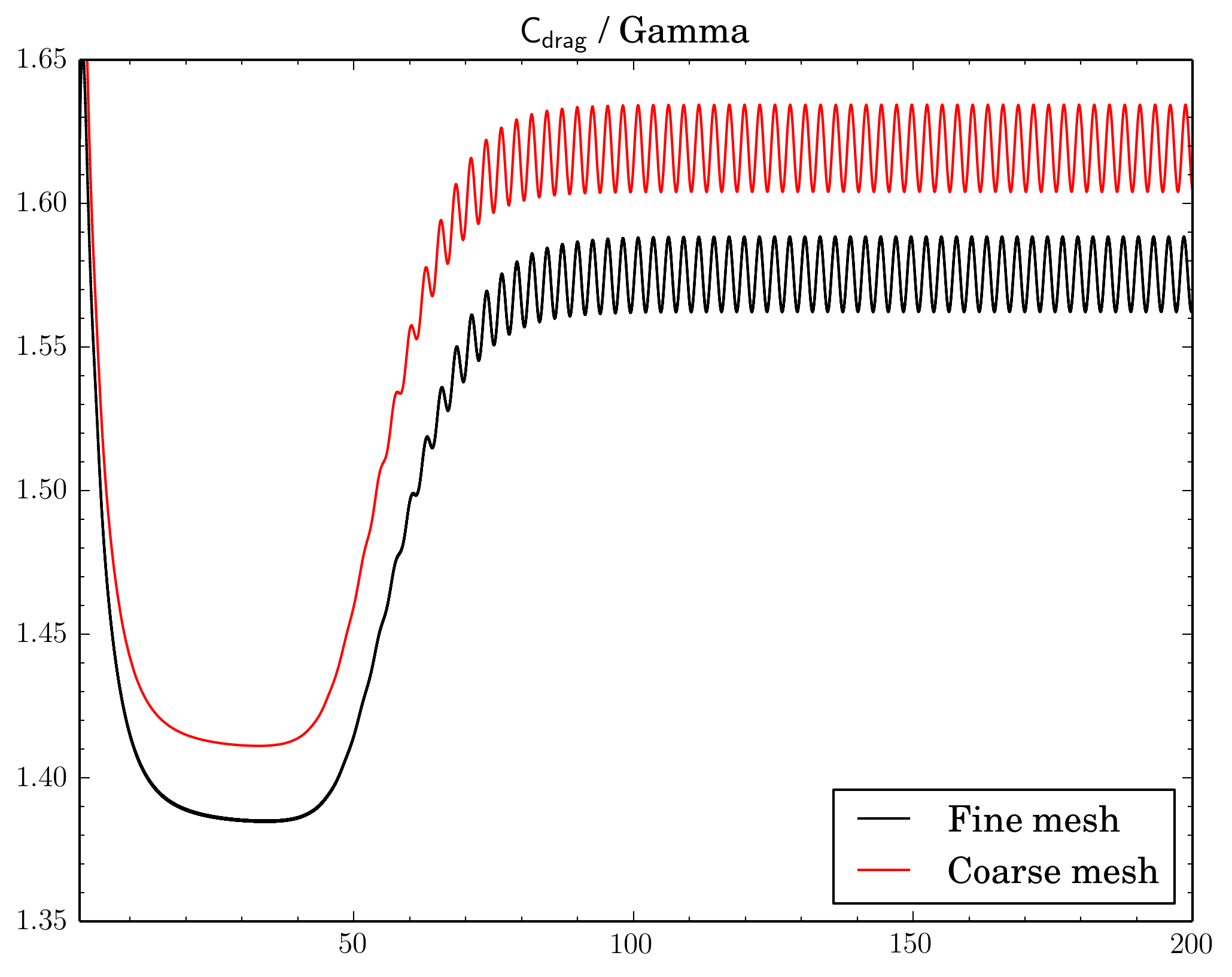
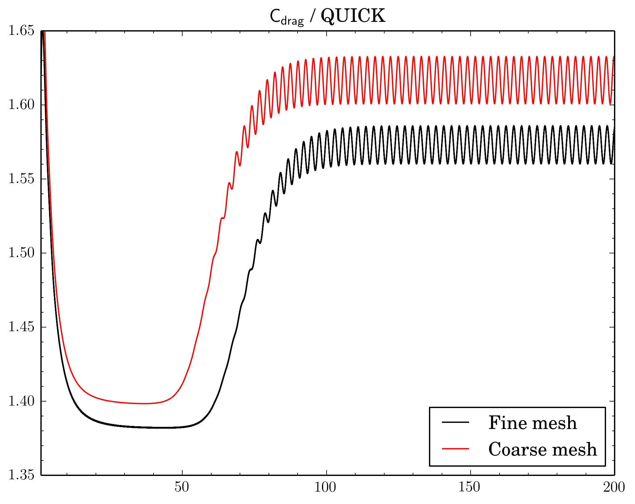
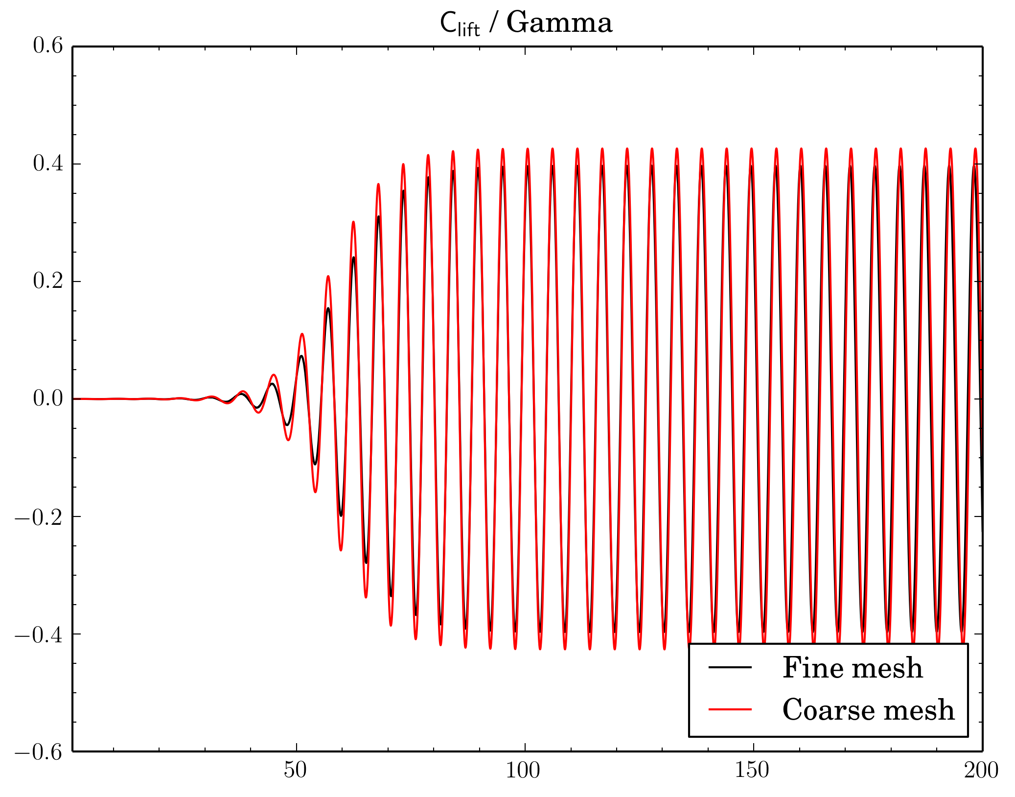
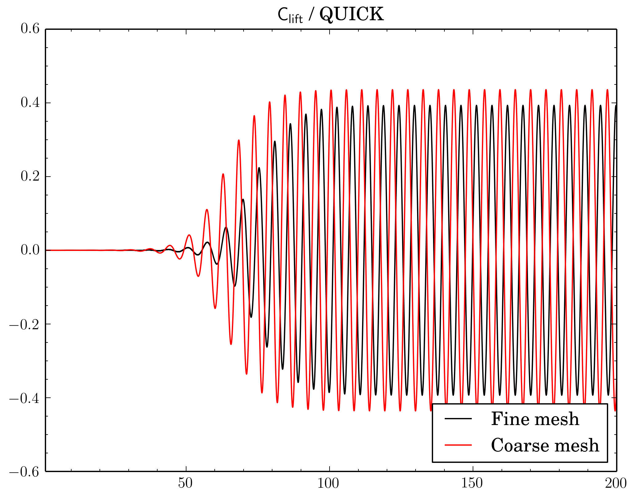
Also compared results acquired using meshes with different densities. Number of cells in the meshes differ 4 times as I've reduced densities twice in X and Y directions.
Gamma showed just decrease of Cdrag and Clift values on fine mesh, while with QUICK and van Leer schemes there's also phase shift between results on different meshes.
Cdrag
Clift
To relax or not
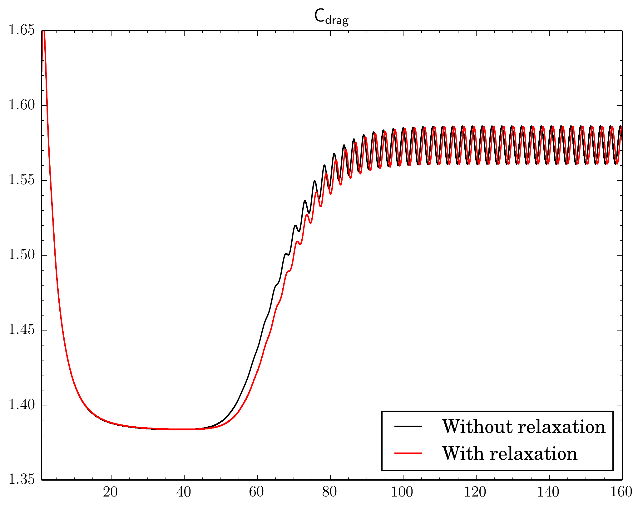
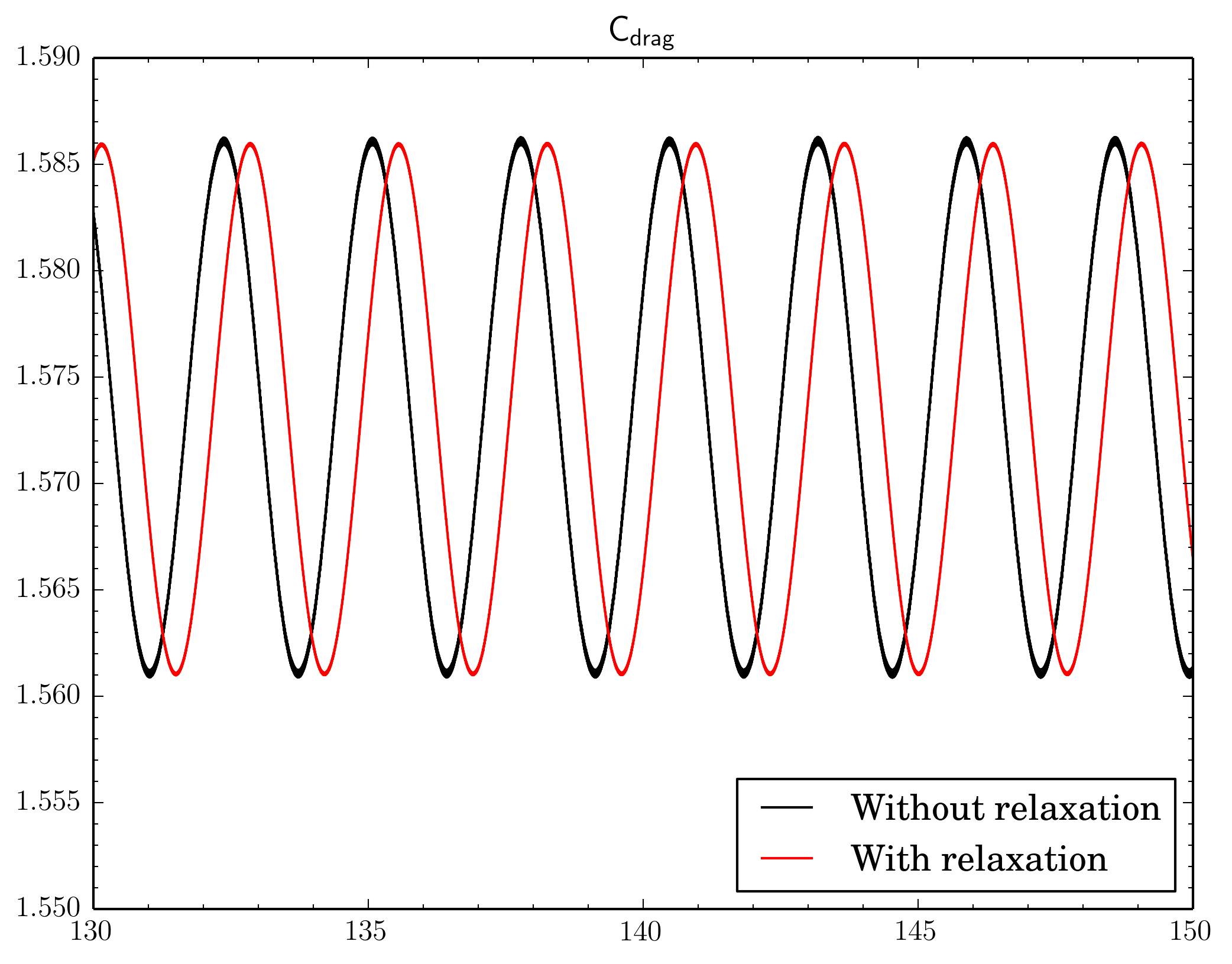
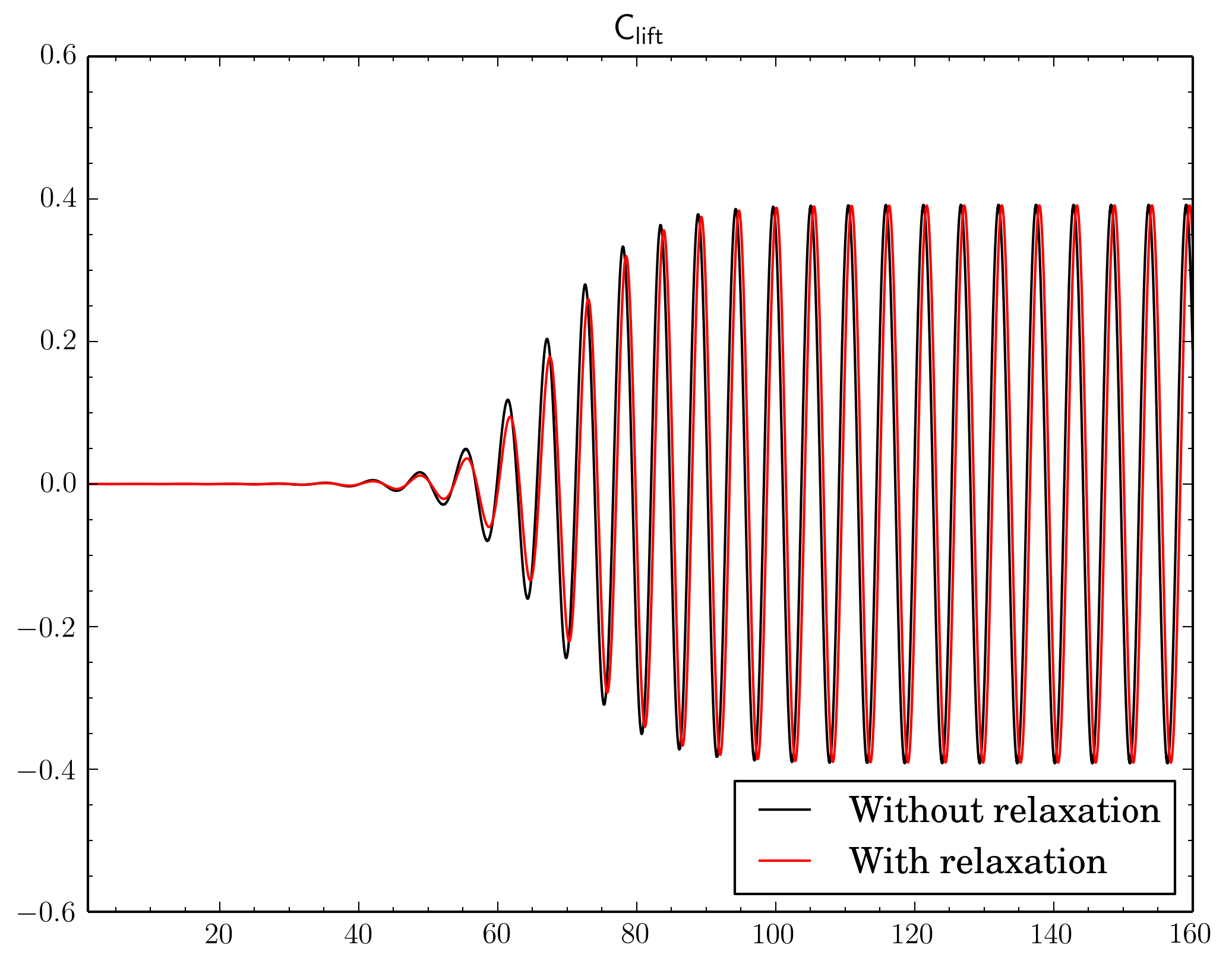
Finally I've decided to check if a relaxation is really crucial to results. I've fixed the discretisation scheme (van Leer, though now I think maybe it was better to choose Gamma), the final residual in
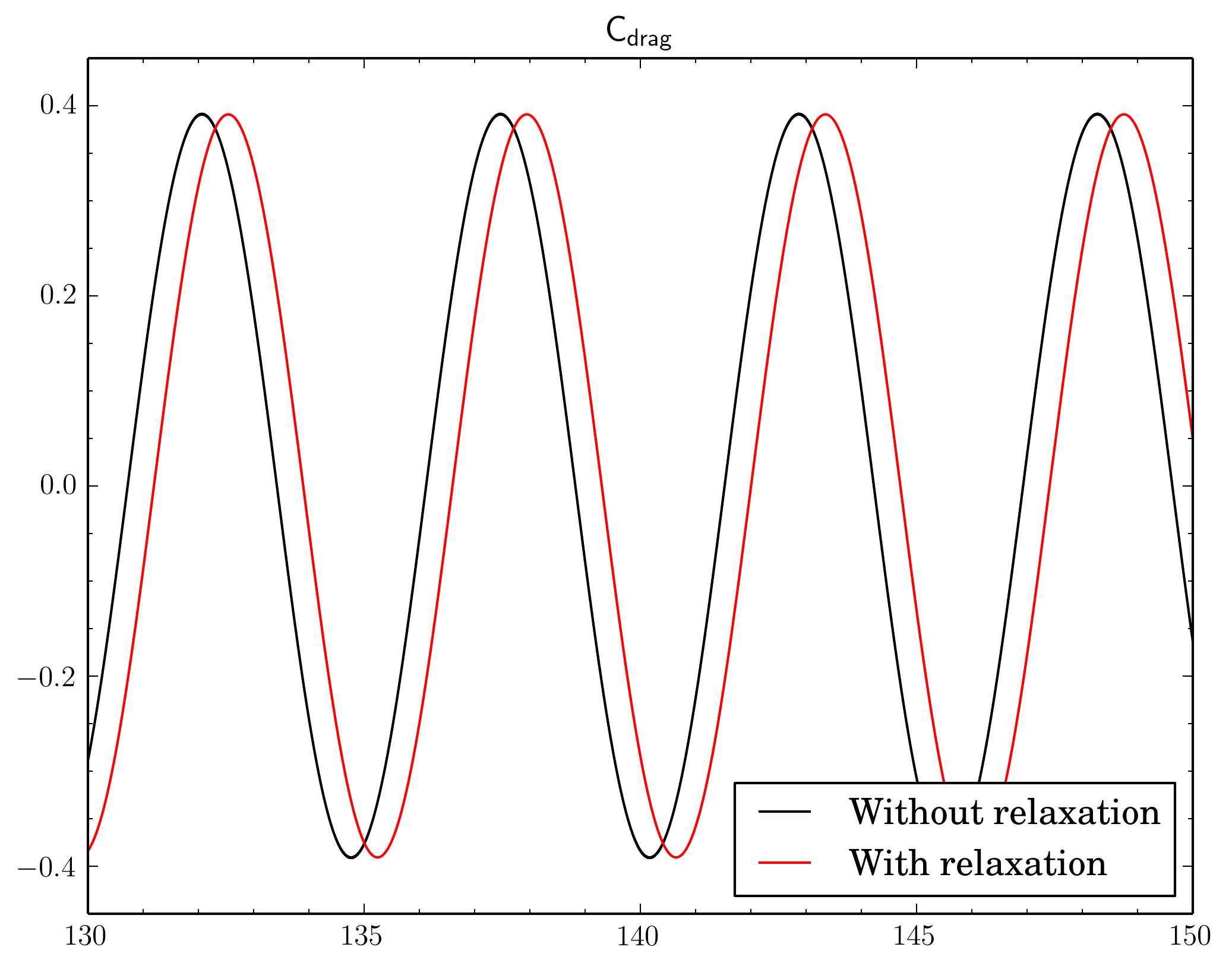
PIMPLE dictionary and just modified relaxation part as shown in the beginning of the post. Surely due to the relaxation solution converges slowly, i.e. instead of 4-5 outer corrector iterations 9-11 iterations was necessary. Also there is a time shift between results.
Conclusion
So it goes.
As usual case files (if you'd like to reproduce results) are on
bitbucket.org.